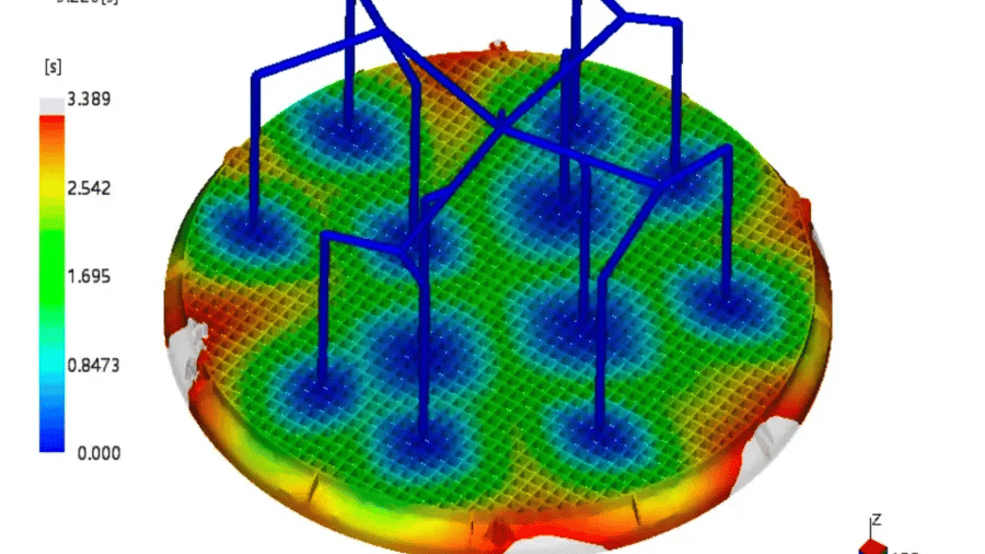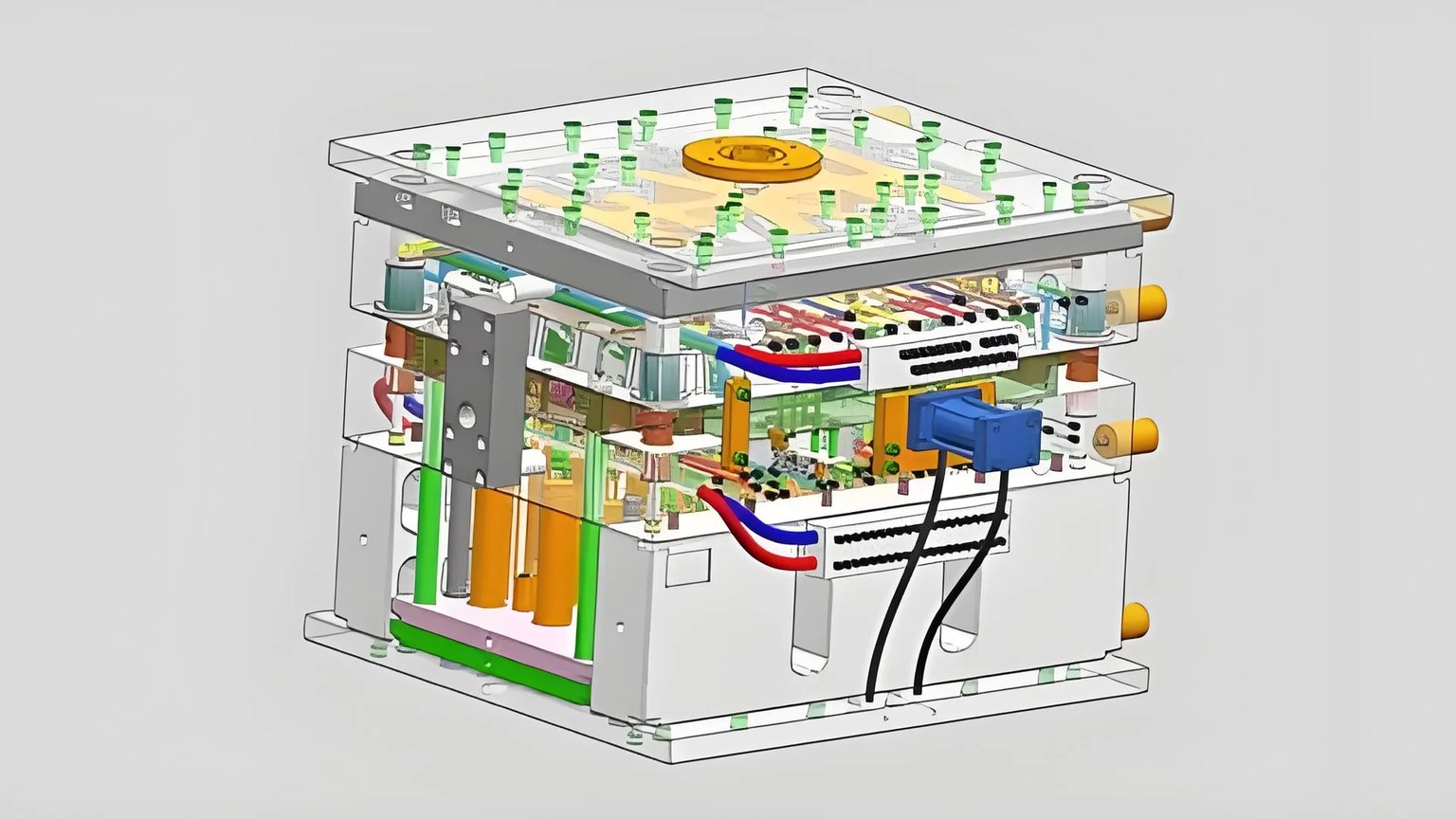
Think about creating a product where every small part is important. The way it stays cool when in use really matters.
Simulation software enhances product cooling analysis by providing detailed insights, optimizing cooling rates, predicting heat distribution, and reducing physical prototyping, ultimately improving efficiency and product quality.
I remember the first time I tried simulation software for cooling analysis. It felt like having a superpower. I could see how temperatures changed across a product. The journey starts with importing a 3D model from CAD software. It’s like opening a new sketchbook full of possibilities. Checking the model for errors is vital. I learned this when a missing part changed my results.
Next is meshing. This process is like weaving a fine net over your creation. Choosing the right mesh size feels like picking the perfect thread count for your sheets. Too big and details are missed; too small, complexity overwhelms. Setting material properties and cooling details follows. Each step contributes to a complete picture showing how your product manages heat.
True wonder appears during the simulation calculation phase. It’s like watching your design come alive with temperature maps and cooling times appearing. This analysis helps spot thermal stresses or inefficiencies. These insights help tweak designs to cut production costs and extend product life.
Tools such as Autodesk Moldflow and ANSYS Polyflow act like trusted partners. Each has unique quirks and strengths. Optimizing cooling channel design or setting boundary limits provides needed clarity. Every tweak through simulation edges closer to perfection. This leads your product to meet real-world challenges successfully.
SolidWorks models must be exported to IGS for simulation.True
SolidWorks models need to be exported to compatible formats like IGS for use in simulation software.
Poor mesh quality improves simulation accuracy.False
Poor mesh quality can lead to inaccurate simulation results or non-convergence of calculations.
- 1. How Do I Set Up a Simulation Model?
- 2. How Do I Choose the Right Material Properties for My Simulation?
- 3. How does cooling system design impact simulation?
- 4. How do you set boundary conditions in cooling simulations?
- 5. Why Should I Analyze Simulation Results?
- 6. What Are the Best Software Options for Cooling Analysis?
- 7. Conclusion
How Do I Set Up a Simulation Model?
Setting up a simulation model feels like putting together a difficult puzzle. This feeling is familiar to me. Dividing the process into small steps simplifies the task.
To set up a simulation model, begin with creating the model. Next, adjust material properties. Configure cooling systems for effective temperature management. Set boundary conditions to define limits. Run calculations to model behaviors. Analyzing results gives insights into performance. It also helps find ways to improve efficiency.

Model Setup
Everything starts here. Importing product geometry models is like building the base of a house. A 3D model made with CAD tools like SolidWorks must fit with your simulation software. One time, I had a model missing a tiny part and it messed up my whole analysis. Checking for missing parts or wrong shapes1 is really important. Check twice!
Meshing
Splitting the model into mesh units is like breaking a big task into smaller tasks. Choose your mesh type and size based on how complex your product is.
| Product Shape | Mesh Type | Mesh Size |
|---|---|---|
| Simple | Coarse | Larger |
| Complex | Fine | Smaller |
Checking mesh quality is always necessary. Bad quality can lead to wrong results.
Material Property Settings
Choosing material properties is like picking the right ingredients for a dish. The software library might have what you need, but sometimes you add them by hand, especially if they are specific. Consider plastic and mold properties like thermal conductivity and density, as these are crucial for simulating heat transfer during the cooling process.
Cooling System Setup
Designing cooling channels mixes creativity with precision. Depending on the mold, set parameters for the cooling medium2 – water or oil. Each one affects flow and heat transfer differently.
Boundary Condition Setup
Initial conditions are like setting the stage for what comes next. These include temperature distributions and conditions like ambient temperature and humidity, which affect how your product changes heat.
Simulation Calculation
Picking the right solver and algorithm is key when running calculations. It’s like choosing the right tool; whether using finite element or difference methods can change efficiency and accuracy. Watching progress helps make quick adjustments.
Result Analysis
After simulations, analyze temperature distribution to understand cooling uniformity and speed. Check cooling time to improve your system more effectively. Conduct thermal stress analysis3 to ensure your product maintains quality and accuracy, cutting production time later.
Export CAD models in IGS format for simulation.True
IGS is a common file format compatible with many simulation tools.
Coarse meshes are used for complex product shapes.False
Complex shapes require finer meshes for accurate simulation results.
How Do I Choose the Right Material Properties for My Simulation?
Ever felt buried under the flood of material choices while preparing for a simulation project? You’re definitely not the only one.
To pick the correct material features for simulation, look at important elements like heat transfer ability, density and specific heat capacity. Material choices affect simulation results. Use the software’s library or add data from suppliers for accuracy.

Importance of Accurate Material Properties
In my early days with simulation software, I learned a crucial lesson: details really matter. Choosing the right material properties is very important. It felt like solving a puzzle with my daughter last winter. Each piece needed to fit perfectly to see the complete picture. Properties such as thermal conductivity4 and density impact the simulation’s accuracy, much like each puzzle piece’s role in completing the image.
Steps for Material Selection
-
Evaluate Material Requirements: Imagine you’re modeling heat transfer in a new gadget. Focus on properties like thermal conductivity5 and specific heat. This is like choosing the right flour for a cake; each kind creates a different texture.
-
Utilize Software Libraries: Most simulation tools have large material libraries. Checking supplier data is essential here – much like confirming a recipe with grandma’s version. If differences appear, you might enter parameters manually from trustworthy sources6.
-
Material Property Calibration: Working with unique materials is like trying a new spice mix. Conduct experiments to measure properties so they match real-world conditions.
| Property | Unit | Typical Range |
|---|---|---|
| Thermal Conductivity | W/(m·K) | 0.1 – 400 |
| Specific Heat Capacity | J/(kg·K) | 700 – 2500 |
| Density | kg/m³ | 700 – 8000 |
Example: Cooling Process in Injection Molding
I remember doing injection molding simulations and seeing the importance of material property choice for cooling efficiency. Picking the right plastic from the software library felt like choosing the perfect hiking boots for a trip – crucial for success. If the library lacked what I needed, I used supplier data provided by reliable sources7.
Tools and Techniques
- Simulation Software: Tools like Autodesk Moldflow or ANSYS helped me get accurate material properties in simulations.
- Data Verification: Like updating phone apps, I kept my software libraries current with material data from trusted sources.
Best Practices
- Do a sensitivity analysis; it’s like tuning an instrument to see how material property changes impact simulation results.
- Record all inputs carefully and cross-check them before running simulations – like proofreading an important email.
By carefully selecting and checking material properties, simulations will more accurately reflect real-world conditions, making design decisions more reliable.
SolidWorks models must be exported as IGS for simulations.True
SolidWorks models should be exported to IGS or STL formats for compatibility.
Coarse meshes are suitable for complex product shapes.False
Complex shapes require finer meshes to ensure accurate simulation results.
How does cooling system design impact simulation?
Remember that scorching summer day when you felt your car’s AC was a lifesaver? Cooling systems in product design serve a similar purpose, keeping everything running without overheating. But how do simulations contribute to this process?
Designing cooling systems using simulations is crucial for optimizing thermal performance before actual production. Engineers study how cooling channels are arranged, examine the properties of materials and consider environmental conditions. Simulations really help improve efficiency and prevent expensive errors. They help reduce mistakes.

Understanding the Basics
Think of a big puzzle where every piece fits perfectly. That’s my experience setting up a cooling system simulation. Everything begins with model setup. I bring in 3D product models from tools like SolidWorks or Pro/E into the simulation software. Models need to be error-free because even one small mistake may cause many issues later.
Then comes meshing – a bit like breaking a giant chocolate bar into small pieces. The type and size of the mesh are very important for the simulation’s accuracy, impacting simulation calculations8. A good mesh reveals how heat travels through the product.
Material Properties and Settings
Once, I had a project with strange plastic materials. It felt like baking a cake without a recipe. Accurate material settings were very important. Thankfully, most simulation software has big libraries of material properties, which saves me from entering data by hand. But at times, I have to dig deep into these settings to make sure everything is perfect.
Cooling System Configuration
Designing the cooling system is my chance to be creative. It’s like drawing a treasure map, where cooling channels are paths to the best performance. Depending on the mold, channels may form complex patterns to cool evenly. I once used curved channels for a tricky mold; it felt like crafting a rollercoaster inside steel!
Choosing the cooling medium is very important too. Setting things like inlet temperature and flow rate is like setting your home’s thermostat; every degree is crucial.
| Parameter | Example Value | Impact on Simulation |
|---|---|---|
| Inlet Temperature | 25°C | Influences initial cooling effectiveness |
| Flow Rate | 2 L/min | Affects the rate of heat dissipation |
| Pressure | 3 bar | Impacts medium flow and heat exchange |
Setting Boundary Conditions
Setting boundary conditions is like planning a road trip. You must know where you start (initial conditions) and the external factors (like weather) that might affect your trip. Similarly, I set conditions such as ambient temperature and humidity that influence heat flow.
Running Simulations and Analyzing Results
Finally, it’s time for the simulation calculation. Watching the solver in action can be both nerve-wracking and exciting. After it’s done, I analyze results like a detective finding clues about temperature and cooling efficiency.
These findings aren’t just numbers; they guide me in refining designs and improving cooling efficiency9. In every project, I see how simulation tools help designers like me explore new ideas and create smarter solutions.
Simulation software requires CAD model import for cooling analysis.True
The process begins with importing a compatible 3D CAD model into the software.
Cooling channels in molds can only be straight pipes.False
Complex molds may use curved or branched cooling channels for efficiency.
How do you set boundary conditions in cooling simulations?
The first time I arranged a cooling simulation for a mold felt like solving a puzzle. Setting the boundary conditions precisely was important. Very important.
Boundary conditions in cooling simulations start with initial temperatures. Experts adjust environmental factors like humidity and convection coefficients. These parameters allow precise thermal analysis. This step is crucial. It is vital for optimizing mold designs. Accurate heat transfer predictions result from this careful process.

Understanding Boundary Conditions
In the early days of my work with simulations, I did not understand how crucial boundary conditions were. They really influence the accuracy of results. These conditions describe how the product interacts with its surroundings during cooling. They control heat flow and cooling speed.
Initial Conditions
Initial temperatures set the scene. For example, I needed the product’s temperature to start exactly from where it was when formed and the mold had to be at room temperature. It’s like ensuring your coffee is at just the right heat before drinking.
Environmental Conditions
Ignoring environmental factors caused me big problems before. Important details like air temperature and moisture really matter. Setting up a convection heat transfer coefficient is like adjusting your home’s thermostat for comfort and efficiency.
| Parameter | Description |
|---|---|
| Initial Temperature | End-of-process temperature for products. |
| Ambient Temperature | Room or preheated state for molds. |
| Convection Coefficient | Heat transfer rate to environment. |
Material Properties
Material properties add more complexity. They affect how fast something heats or cools. It’s like knowing how different breads toast in your toaster – some really need more time.
Defining boundary conditions correctly is very important. This helps to reflect real situations in cooling simulations, ensuring designs function well, not only on paper but also in reality.
Impact on Simulation Accuracy
I have experienced how bad boundary setting gives wrong results; it affects product quality. Once, I guessed wrong about air settings, which almost led to a cooling problem that was luckily caught in time.
Choosing the correct solver and algorithm is like finding the best route on a GPS; it impacts how boundary conditions affect the simulation. Right methods improve speed and accuracy.
For people who want to learn more about setting boundary conditions well, check out this resource10 for advanced tips.
Understanding these parameters is essential for trustworthy simulation outcomes. This knowledge helps improve mold designs effectively, streamlining production and helping foresee issues before manufacturing starts.
Importing CAD models requires compatible file formats.True
CAD models must be exported to formats like IGS or STL for simulations.
Coarser meshes are used for complex product shapes.False
Complex shapes require finer meshes for accurate simulation results.
Why Should I Analyze Simulation Results?
Have you ever asked yourself why studying simulation results changes everything for designers? Simulation results offer insights that designers often miss. These results reveal important details. They help catch mistakes early. Designers save time and energy by understanding these details. Time and energy are very valuable. Predictions based on simulations allow for better decisions. Better decisions lead to improved designs. Improved designs satisfy more people.
Examining simulation results is vital for better product design. It improves performance and lowers costs. This process predicts possible problems. It also perfects methods before real testing happens.
Improving Product Performance
I remember seeing the power of simulation analysis. It was like having a crystal ball, revealing how designs perform in real-life conditions. By studying temperature spread11 and thermal stress, designs became more functional and reliable before building a prototype. Very useful.
Streamlining Design Processes
Time and resources are greatly saved through simulation. Once, I worked on a cooling system. Changing the cooling channel design after looking at simulation data12 made manufacturing smoother. It was eye-opening. Simulations offer great potential.
| Design Aspect | Benefit of Analysis |
|---|---|
| Cooling Channel | Improved flow and heat distribution |
| Material Selection | Enhanced thermal conductivity |
| Boundary Conditions | Accurate environmental simulations |
Saving Costs
Catching issues early saves money. I remember finding a geometry error during a simulation. Fixing it early saved thousands on materials. Detecting errors beforehand cuts costs and avoids manufacturing problems.
Better Decision-Making
Simulation results provide insights for decisions that match production goals. Evaluating cooling time13 or thermal stress data gives me the knowledge to choose confidently. Knowledge empowers.
Spotting Potential Problems
Results analysis isn’t just about finding issues; it’s about stopping them from growing. Fixing potential thermal stress or bending early keeps the final product strong throughout its life, ensuring higher quality outcomes and maintaining structural integrity.
Encouraging Innovation
Simulations open doors for innovation by providing a platform for experimenting with new ideas without the big cost of physical models. It’s a place for creativity where concepts14 can be tested freely, turning the fear of failure into a thrill of discovery—truly exciting.
Simulation software requires compatible 3D model formats.True
Simulation software needs models in formats like IGS or STL for analysis.
Coarse meshes are used for complex product shapes.False
Finer meshes are needed for complex shapes to ensure accurate results.
What Are the Best Software Options for Cooling Analysis?
Do you ever feel confused by the many cooling analysis programs available? Others feel this way too. Let’s look at the best options and find which one could really suit you.
Top cooling analysis software includes Autodesk Moldflow, Moldex3D and ANSYS Polyflow. These tools shine in simulating heat flow. They really match industry standards. Each offers unique strengths. Yes, unique strengths.

Understanding Software Features
When I first explored cooling analysis15 software, I felt like a kid in a candy store – unsure where to start but thrilled by the possibilities. Each software has its unique charm. Autodesk Moldflow, for example, acts like that dependable friend who makes things easier with its user-friendly design and thorough simulations. Moldex3D, meanwhile, feels like entering a cutting-edge lab with advanced 3D viewing tools, letting you see cooling paths as if you were there. On the other hand, ANSYS Polyflow provides a treasure chest of detailed material properties, guiding you to predict material behavior with precision.
Steps for Cooling Analysis
Starting the cooling process is quite an adventure. It’s like assembling a complex puzzle, where each piece must fit perfectly. Here’s how I usually proceed:
-
Model Creation
- Bringing in product geometry models feels like laying down the blueprint for a house. The model from CAD tools like SolidWorks needs to be just right – no parts or errors missing.
- Then, meshing happens. It feels like shaping digital clay, forming finer or larger meshes based on the design’s complexity.
Software Geometry Import Mesh Quality Check Autodesk Yes Automated Moldex3D Yes Manual/Automated ANSYS Yes Detailed Control -
Material Property Selection
- Selecting materials resembles picking ingredients for a recipe; they must perfectly match your simulation needs.
-
Cooling System Planning
- Designing cooling channels is like playing a strategic game. Correct parameters make a big difference.
Results Analysis
Finally, the detective work begins. I examine temperature distributions, cooling times and thermal stress after running the simulation. It’s fascinating to see how small design changes can optimize everything – from proper temperature distribution to lowering thermal stress.
- Temperature Distribution: Visualize using cloud maps.
- Cooling Time: Adjust design to optimize.
- Thermal Stress: Evaluate deformation risks.
Tweaks matter. They really do.
Considerations When Picking Software
On my journey to choose the right software, I learned that factors like user interface and cost significantly influence my decisions. I usually check user forums and professional communities16 for real-world insights – they provide valuable advice and troubleshooting tips.
Finding the right software is like finding a partner in crime – it should fit your workflow and improve your efficiency. Once you make this decision, you’re ready for a more streamlined and accurate design process.
IGS and STL are common formats for simulation imports.True
IGS and STL are widely used formats compatible with simulation software.
Poor mesh quality enhances simulation accuracy.False
Poor mesh quality can lead to inaccurate simulation results.
Conclusion
Simulation software enhances product cooling analysis by providing insights into temperature distribution, cooling efficiency, and thermal stress, ultimately improving design quality and reducing production costs.
-
Ensuring model integrity prevents errors in simulation results by confirming geometry accuracy. ↩
-
Learn how cooling mediums influence heat transfer, crucial for optimizing thermal efficiency. ↩
-
Understanding thermal stress helps in predicting potential deformation, ensuring product reliability. ↩
-
This link explains why thermal conductivity is critical in simulations, especially when modeling heat transfer scenarios. ↩
-
Discover how to accurately input supplier-provided material data into your simulation software for enhanced model accuracy. ↩
-
Find reliable sources for obtaining the latest material property data to keep your simulation software libraries current. ↩
-
Explore techniques for verifying all inputs in your simulations to ensure their accuracy and reliability. ↩
-
Discover why meshing is crucial for accurate simulations and how it affects model calculations. ↩
-
Learn strategies for enhancing cooling system efficiency through simulation-driven design adjustments. ↩
-
Discover advanced techniques for improving simulation accuracy and efficiency. ↩
-
Understanding how simulation data impacts product performance can guide design enhancements for improved reliability. ↩
-
Explore how simulation data aids in optimizing cooling systems for efficiency and effectiveness. ↩
-
Discover how simulations can fine-tune cooling times, enhancing production efficiency. ↩
-
Learn how simulations encourage innovative engineering solutions by enabling experimentation. ↩
-
Learn about Autodesk Moldflow’s features and capabilities in cooling analysis to determine if it suits your project needs. ↩
-
Engage with community discussions to gain real-world insights into the software’s performance and practical usage tips. ↩


