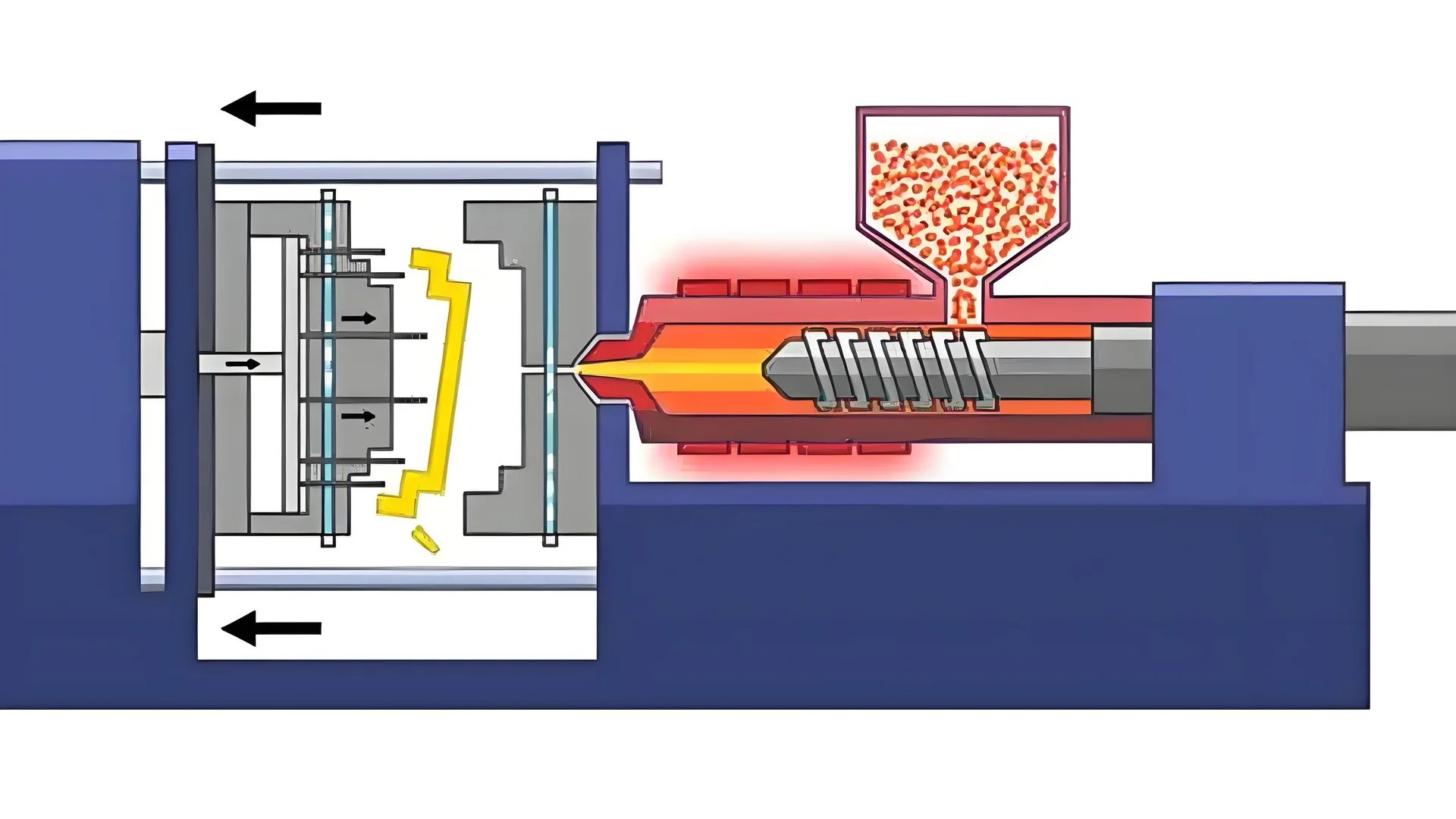
Ever wondered how plastic becomes everyday items like toys or phone cases?
When plastic is injected into a mold, it is heated until molten, then forced into a mold cavity under high pressure. The material cools and solidifies, taking the shape of the mold, creating precise, durable parts ready for use in various applications.
In the beginning, I explored plastic injection molding and felt surprised by the hidden details. Each step became important, like the flow of plastic at different speeds and temperatures. Even little changes in design often led to better product quality. Mastering these subtleties truly brings satisfaction.
Plastic melt flows faster at the main channel's center.True
The melt flows faster at the center due to less friction.
Gates reduce plastic melt temperature by increasing viscosity.False
Gates increase shear, raising temperature and reducing viscosity.
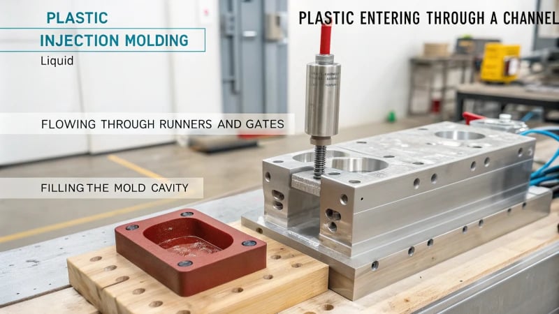
How Does Plastic Enter the Mold?
Have you ever thought about how plastic goes into a mold to become the gadgets we enjoy? This process is very interesting!
Plastic travels into the mold through many pathways. First, plastic goes through the main channel. Then, it moves through runners and gates. Finally, it fills the cavity. Each step is important. Each step changes flow rate, pressure and distribution. All these are crucial for filling the mold perfectly. Yes, perfect filling.

Initial Stage of Flow at the Entrance
I remember my first day at the mold factory, amazed by how plastic pellets turned into shiny electronics. It begins with plastic being pushed into the main channel by the injection machine’s screw or plunger. Imagine squeezing toothpaste into a tube, but with much more precision. The pressure is strong and as plastic shoots through the conical main channel, it forms a velocity gradient. It’s similar to cars moving faster in the middle lane and slowing down near the curb.
Flow in the Runner
After that initial rush, the plastic goes into the runner. Imagine a river splitting into streams to supply each part of the mold with plastic. I discovered how vital runner design really is. Circular runners help reduce pressure loss, allowing smooth flow. It’s like pouring coffee perfectly, without spills, following precise flow laws to maintain balance.
Flow at the Gate
The gate is where things get even more important. It’s a tiny entrance controlling the plastic’s speed and amount into the cavity. Picture a barista managing espresso shots. As plastic squeezes through, it speeds up due to pressure, heating up and flowing better. Various gates create different effects; side gates allow gentle entry, while point gates can cause a rapid burst.
Flow in the Cavity
Finally, we arrive at the cavity. It becomes tricky here. Factors like cavity shape and wall thickness challenge flow behavior. I’ve seen designs struggle due to uneven thickness, like trying to fill an irregular ice cube tray neatly. Consistent thickness keeps flow steady. But if walls vary or have features like ribs, it’s a different game. Streams might collide poorly, leaving weld marks – those annoying lines that hurt both appearance and function.
| Stage | Description | Key Factors |
|---|---|---|
| Entrance | Main channel entry | Pressure, axial flow |
| Runner | Distributes melt | Shape (e.g., circular), size |
| Gate | Controls flow entry | Throttling, shear rate |
| Cavity | Final filling | Wall thickness, complexity |
Knowing these stages really helps me and other designers improve plastic flow dynamics1 for high-quality production results. It’s like perfecting a dance – the smoother the movements, the better the final performance.
Plastic flows faster at the center of the main channel.True
Due to shearing, the plastic melt flows faster at the center.
A point gate makes plastic flow gently into the cavity.False
Point gates cause plastic to enter in a jetting manner, not gently.
How Do Runners Shape Injection Molding?
Visualize conducting a complicated symphony of liquid plastic. Every part has to land exactly in the right spot in the mold holes.
Runners in injection molding are important paths. They guide melted plastic from the injection machine to the mold spaces. Design of these runners affects how fast the plastic moves. It also influences pressure spread and how much material is used. Efficiency is really crucial here.

The Initial Flow Dynamics
Imagine molten plastic starting its journey through the main path, pushed along by the injection machine’s screw or plunger. It’s like observing a river where water moves quickly in the center, while the sides move more slowly. This early flow pattern determines how evenly the material spreads into the system of runners2. This step is very important for uniformity.
The Role of Runner Design
From my view, runners are important pathways that help each mold section get an equal amount of plastic melt. Visualize them as different routes on a hiking path – circular, trapezoidal or U-shaped. Each shape guides the flow in its distinct manner. Circular runners resemble flat, easy trails with low pressure drop and a smooth journey all through.
| Runner Shape | Characteristics |
|---|---|
| Circular | Even flow, low pressure loss |
| Trapezoidal | Varies with mold design |
| U-shaped | Specific applications for unique molds |
Influence on Material Flow
Here’s a little-known fact: understanding Poiseuille’s law is really like having special access to fluid dynamics secrets. Similar to liquid in a tube, plastic melt speeds up at the center of the runner and slows near the walls. This expected pattern is what designers depend on when planning those flow rates3 that really set production apart.
Connection to the Mold Cavity
Runners connect to gates – the small gatekeepers controlling how the plastic melt fills each cavity. Side gates allow a slow approach, while point gates act like quick entries. Knowing these differences is key, especially for designing complex components with gentler transitions4.
Practical Considerations
Selecting the appropriate runner design is like piecing together a puzzle. It requires balancing quickness and efficiency while keeping design limits in mind. Mastering this choice not only refines molds but also improves performance and saves money in mass production. This knowledge helps designers optimize molds5 for both cost and performance.
The main channel is typically conical in shape.True
Most main channels are conical, aiding axial flow of plastic melt.
A point gate causes melt to enter the cavity gently.False
Point gates cause a jetting manner of melt entry, not gentle flow.
How does the gate affect plastic flow?
A small gate sometimes decides if a plastic piece succeeds or fails.
The gate controls how fast and how much plastic melt enters the cavity. This affects shear rate, temperature and the quality of the molded product. Designers must refine gate design for good plastic flow.

Beginning of Flow at the Gate
When I learned about injection molding, it felt like a big orchestra. The plastic enters through the main channel, pushed by the screw or plunger. It sets the stage. The shearing forces6 act like tuning an instrument and decide how the melt moves.
Flow in the Runner
In the runner, the melt behaves like a river splitting into streams. Each shape—circular, trapezoidal, or U-shaped—changes the flow in its own way. Once, I worked on a project changing the runner from U-shaped to circular. It really lowered pressure loss, like switching from gravel to a smooth road on a bike trip.
| Runner Shape | Flow Characteristics | Pressure Loss |
|---|---|---|
| Circular | Even flow | Minimal |
| Trapezoidal | Moderate flow | Moderate |
| U-shaped | Uneven flow | High |
Flow at the Gate
The gate is magical. Its job involves controlling how fast the melt goes in, like a conductor leading music. Different gates affect the flow uniquely; point gates7 cause fast, dramatic entry while side gates have a calmer flow.
Flow in the Cavity
The cavity seems like a maze. Uniform wall thickness leads to smooth flow and fills all parts nicely. But ribs or undercuts create a bumpy path.
| Cavity Feature | Effect on Flow |
|---|---|
| Uniform Walls | Stable laminar |
| Ribs/Undercuts | Altered paths |
Understanding this was key when dealing with weld marks—those ugly lines where streams meet awkwardly.
Reflecting on these times, I see every part of the flow improves product quality. It’s about crafting solutions and involves bettering manufacturing methods for efficiency and looks.
Plastic flows faster at the center of the main channel.True
The center of the main channel experiences less shear, allowing faster flow.
Point gates allow for a gentle entry into the cavity.False
Point gates cause melt to enter the cavity in a jetting manner, not gently.
What Happens Inside the Cavity During Molding?
Curious about the happenings inside a mold cavity? It is a little journey for plastic. Raw material changes form to become common items.
During molding, the hot plastic flows into the empty space. The cavity’s shape, the walls’ thickness and how fast it cools all affect this flow. These factors shape the finished product’s form and quality. Problems may appear, like seams on the surface or areas filling with different speed. These issues need careful attention. Very careful.

Initial Flow Dynamics
When learning about injection molding, the start of the process amazed me. Picture plastic entering the main path, driven by the screw of an injection machine. At this point, the melt moves quickly under high pressure. The channel, shaped like a cone, causes different speeds – near the edges, flow slows down while the center speeds ahead. It looks like a river speeding through a narrow gorge! Understanding this flow8 is crucial as it sets the tone for subsequent stages.
Flow in the Runner
The journey moves into the runner, reminding me of a complex road system. Whether round or U-shaped, these paths are important for spreading the melt evenly to each cavity. Fluid mechanics laws govern this smooth flow, with the center moving faster than the edges. Imagine rush hour traffic in a busy city; it’s very similar.
-
Runner Shape Effects:
Shape Flow Characteristics Circular Even distribution, low pressure loss Trapezoidal Varies depending on size and roughness
Gate Flow Dynamics
Next is the gate – a small passage with big tasks. It controls how fast the melt enters the cavity. Different gates cause different flow styles; side gates allow gentle entry, while point gates might cause a sharp stream. This step is crucial; it’s like adjusting a garden hose nozzle for the perfect spray—a very careful adjustment.
Inside the Cavity
Finally, the plastic reaches the cavity where exciting things happen. As the melt moves, it exchanges heat with cavity walls, cooling and thickening. If you’ve baked a cake, you know how important even heat is to avoid cracks—same here.
- Cavity Shape and Thickness: Uniform wall thickness helps smooth flow; differences might cause disturbances.
-
Heat Exchange: As it cools down and increases viscosity.
Factor Impact Wall Thickness Affects flow stability and cooling rate Reinforcements & Undercuts Cause flow redirection and merging
These small details might lead to problems like weld marks if streams merge improperly—similar to clothing seams not lining up perfectly. Understanding these dynamics has greatly improved my design skills and product quality. Each mold feels like solving a new puzzle! Exploring solutions for weld marks9 further improves product finish and strength.
Plastic melt flows faster at the center of the main channel.True
The center of the main channel has less shear resistance, allowing faster flow.
All types of gates cause the melt to enter the cavity gently.False
Point gates cause jetting, while side gates allow a gentler flow into cavities.
How Can Designers Optimize Injection Molding?
Ever felt the stress of achieving that flawless plastic part? Designers probably know every choice changes the injection molding process. Here is my story of perfecting this skill.
I focus on designing efficient molds to optimize injection molding. Choosing the right materials is very important. Adjusting process parameters like temperature and pressure really helps. This reduces waste. Product quality improves.

Understanding Flow Dynamics
I recall the first time I saw plastic melt into a mold – it resembled a tiny river taking form. The beginning is crucial; plastic moves through the main channel, directed by the injection machine’s screw. It is fascinating how the melt moves faster in the center and slows near the edges. Less waste and smoother transitions really need good flow. Optimizing this stage ensures smoother transitions with a velocity distribution10 due to shearing.
Designing Efficient Runners
Figuring out the runner felt like solving a puzzle for me. I always chose a circular runner shape because it keeps the flow steady and cuts down on pressure loss, maintaining laminar flow and ensuring uniform distribution. It reminded me of those smooth highway curves that let you glide without losing speed. Designers can refer to flow dynamics in runners11 for deeper insights.
Gate Design for Optimal Flow
Picking the right gate was like finding the best route on a twisty road. Different gates manage how quickly and smoothly the melt reaches the cavity.
| Gate Type | Flow Characteristics |
|---|---|
| Side | Gentle, gradual entry |
| Point | Quick, jetting entry |
For example, a point gate12 feels like pushing the gas pedal, while a side gate offers a more relaxed ride.
Managing Cavity Complexity
The cavity is where things become very intriguing – and difficult. I’ve seen that even small changes in wall thickness can change the flow, just like how weather changes your travel speed. Uniform thickness is crucial as it avoids those bothersome weld marks that destroy an otherwise great product. Addressing potential weld marks13 during design can enhance final product quality.
Material Selection and Process Parameters
Deciding on materials is like picking the right ingredients for a dish – each impacts the final result. Tweaking temperature and pressure feels like adjusting oven settings for the perfect bake. I always return to material selection criteria14 to stay focused.
Improving injection molding involves considering every phase – from choosing materials to altering process parameters15. Understanding this complexity has probably not only improved my efficiency but also enhanced both efficiency and product quality.
Plastic melt flows faster at the main channel center.True
The melt flows faster in the center due to higher pressure and shearing.
Circular runners cause higher pressure loss than other shapes.False
Circular runners have lower pressure loss and distribute melt evenly.
Conclusion
The plastic injection molding process involves injecting molten plastic into a mold through various stages, including the main channel, runner, gate, and cavity, ensuring precision and quality in production.
-
Provides comprehensive information on flow dynamics, aiding in better design and production strategies. ↩
-
Understanding initial flow dynamics can help improve molding efficiency by reducing defects. ↩
-
Exploring runner shapes aids in optimizing flow rates and reducing waste. ↩
-
Comparing gate types can guide in selecting the appropriate gate for desired flow. ↩
-
Optimizing mold design can significantly reduce production costs and time. ↩
-
Discover how shear forces influence melt behavior during injection molding, affecting flow dynamics and product quality. ↩
-
Learn how point gates facilitate jetting flow in cavities and their impact on molded part aesthetics. ↩
-
Learn how velocity distribution impacts flow dynamics in molding, setting the foundation for quality end products. ↩
-
Find strategies to reduce weld marks, enhancing product aesthetics and structural integrity. ↩
-
Explore this link to understand how velocity distribution affects mold filling and part quality. ↩
-
Learn about runner system designs that enhance flow efficiency and reduce energy consumption. ↩
-
Discover how point gate designs impact melt flow speed and application suitability. ↩
-
Find strategies to reduce weld marks for improved surface finish and structural integrity. ↩
-
Understand key factors in selecting materials for enhanced performance and longevity. ↩
-
Gain insights on adjusting temperature and pressure to reduce defects and waste. ↩


