Imagine sculpting a piece of art where every curve and edge dictates the tools you’ll use. That’s how part geometry influences mold design in injection molding.
Part geometry impacts injection mold design by affecting flow, cooling, and ejection, leading to potential complexity and cost changes. Understanding these effects helps optimize molds for efficiency and manufacturability.
I remember the first time I tackled a complex geometry for a project—it was like a puzzle that required precise thinking. The undercuts were tricky, and I had to adjust the wall thickness to avoid potential flaws. These elements, along with draft angles, are crucial in refining mold design. By considering these nuances, we can improve efficiency and product quality, making each design a rewarding challenge.
Part geometry affects mold flow in injection molding.True
Different shapes impact how material flows within the mold.
Mold complexity decreases with intricate part geometry.False
Complex geometries typically increase mold complexity, not decrease it.
- 1. How Do Geometrical Features Influence Mold Design?
- 2. How Do Undercuts Influence Mold Complexity?
- 3. Why is Wall Thickness Important in Mold Design?
- 4. How Do Draft Angles Affect Mold Ejection?
- 5. What Role Does Part Symmetry Play in Designing Molds?
- 6. How Can Designers Optimize Molds for Complex Geometries?
- 7. Conclusion
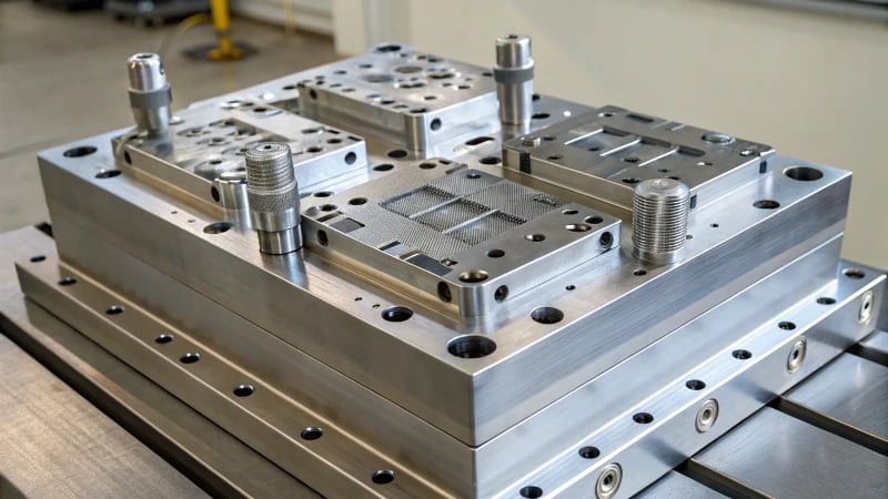
How Do Geometrical Features Influence Mold Design?
Ever wondered how those intricate molds come to life? It’s all about the details in design.
Geometrical features like wall thickness, mold size, core shapes, and part complexity are vital in mold design, affecting manufacturability, cooling efficiency, and product quality.
Wall Thickness
I remember the first time I realized the importance of wall thickness. I was working on a project for a sleek new gadget, and the client was adamant about its unique curves. But what looked good on screen was a nightmare in practice—warping was rampant because we hadn’t considered uniform wall thickness. A consistent wall thickness ensures even cooling and minimizes warping, which is vital. Varying thicknesses can lead to unexpected stress concentrations and defects, as I learned the hard way.
| Wall Thickness | Impact on Design |
|---|---|
| Uniform | Even cooling, reduced warping |
| Varying | Stress concentrations, defects |
Mold Size
Size does matter, especially when it comes to molds. Once, I designed a massive mold for an automotive part. It was impressive but incredibly resource-intensive. Larger molds consume more material and take longer to cool, directly affecting efficiency and cost. We need to strike a balance between size and material usage for optimal material utilization1.
Core Shapes
Oh, the tales of core shapes! I recall a time when a complex core design almost derailed a project. The ejection process was tricky because of its intricate geometry. Precision in selecting core shapes can significantly enhance production efficiency2, turning potential pitfalls into smooth operations.
Part Complexity
The more complex the part, the more challenges arise in mold design. During one project, the complexity of our designs meant more molds and increased costs, but the result was worth it—a highly detailed product that stood out.
| Complexity Level | Design Challenges |
|---|---|
| Simple | Fewer molds, lower costs |
| Complex | More molds, higher costs |
Understanding these geometrical nuances has been a journey for me, learning to optimize molds for enhanced performance while keeping production costs in check. By analyzing these factors3, I’ve been able to make informed design decisions that have saved both time and resources in the long run.
Uniform wall thickness reduces warping in molds.True
Uniform wall thickness ensures even cooling, minimizing warping.
Complex core shapes simplify the ejection process.False
Complex core shapes complicate ejection, requiring precise planning.
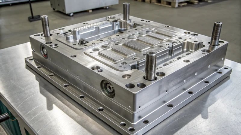
How Do Undercuts Influence Mold Complexity?
Navigating the intricacies of mold design is a journey where undercuts often become intriguing puzzles, shaping both complexity and cost.
Undercuts in mold design increase complexity by requiring side actions or lifters, complicating ejection, and raising costs. Strategic design is essential to effectively manage these challenges.
Understanding Undercuts in Mold Design
I remember the first time I encountered an undercut in a mold design. It was like meeting a new character in a novel—unexpected and full of potential twists. Undercuts, those fascinating features that keep parts snugly in place, can turn a straightforward mold design into a complex challenge. They demand additional mechanisms such as side actions or lifters to release the part, upping the ante on complexity and cost. It’s like trying to solve a puzzle where every piece must fit perfectly, or the whole picture falters.
| Aspect | Impact of Undercuts |
|---|---|
| Design | Requires complex tooling designs to accommodate undercuts. |
| Production | Increases cycle time due to additional steps in the ejection process. |
| Cost | Elevates costs due to more intricate molds and maintenance. |
Solutions for Managing Undercuts
-
Side Actions and Lifters:
These crafty components move parts of the mold during ejection, much like adjusting gears in a clockwork to align everything just right.- Pros: Enable complex designs; offer flexible solutions.
- Cons: Can escalate mold maintenance and wear.
-
Part Redesign:
Sometimes, it’s about going back to the drawing board, quite literally! By tweaking angles or eliminating unnecessary features, I find that simplifying designs can significantly reduce complexity. -
Advanced CAD Software:
Harnessing the power of advanced CAD tools is like having a crystal ball. They reveal potential undercut issues early on, allowing adjustments before they morph into larger headaches.
Real-World Applications
In my experience, working with industries like automotive or consumer electronics is where undercuts frequently emerge. They’re essential for creating unique textures or latch mechanisms that enhance both function and aesthetics. Designers might use undercuts4 to achieve that perfect finish or functionality, balancing on the edge of innovation and practicality.
Understanding how undercuts influence5 mold complexity allows designers like myself to make informed decisions, striking the right balance between visual appeal and manufacturability.
Undercuts require side actions in mold design.True
Side actions are used to manage undercuts, allowing for part ejection.
Part redesign is unnecessary for mold simplification.False
Redesigning parts can simplify molds by eliminating undercuts.
Why is Wall Thickness Important in Mold Design?
Ever wondered why wall thickness is such a big deal in mold design? It’s more important than you might think for creating quality products.
Wall thickness in mold design is vital for uniform cooling, material flow, and structural integrity, reducing defects like warping and cracking, ultimately improving the quality and reliability of injection-molded products.
The Role of Wall Thickness in Cooling Rates
When I first delved into mold design, the impact of wall thickness on cooling time was a revelation. I remember working on a project where we struggled with extended cycle times because our walls were just too thick. Thicker walls hold onto heat longer, which means they take forever to cool down. This not only drags out production time but also messes with shrinkage consistency. I quickly learned that keeping wall thickness uniform6 was key to maintaining a smooth cooling process and minimizing those pesky defects.
Impact on Material Flow and Structural Integrity
Imagine trying to pour pancake batter through a funnel that’s too narrow—it’s just not going to flow properly! That’s kind of how I see material flow in mold design. Thin walls can choke the flow, leading to incomplete fills. On the flip side, when walls are too thick, you end up with sink marks and waste a ton of material. Finding that sweet spot is crucial to ensuring the finished product has adequate strength7 yet still looks great.
| Wall Thickness | Cooling Rate | Material Flow |
|---|---|---|
| Too Thick | Slow | Risk of Sink Marks |
| Ideal | Balanced | Optimal |
| Too Thin | Rapid | Risk of Warping |
Avoiding Defects: Warping and Cracking
One time, I was part of a team working on a design that kept cracking after production. We couldn’t figure it out until we realized the wall thickness was uneven, causing different parts to cool at different rates. This created internal stresses, leading to warping and cracks. Since then, I’ve always made it a point to use CAD tools for analyzing potential weak points8 and ensuring consistent wall thickness throughout a component.
In conclusion, paying attention to wall thickness from the get-go is vital in mold design. It helps balance production efficiency with product durability and quality, cutting down on defects like warping and cracking. As designers, incorporating these principles early in the design process can really make or break the success of our projects.
Thicker walls increase cooling time in molds.True
Thicker walls retain heat longer, extending the cooling process.
Uniform wall thickness leads to warping in products.False
Uniform thickness minimizes defects like warping, ensuring reliability.
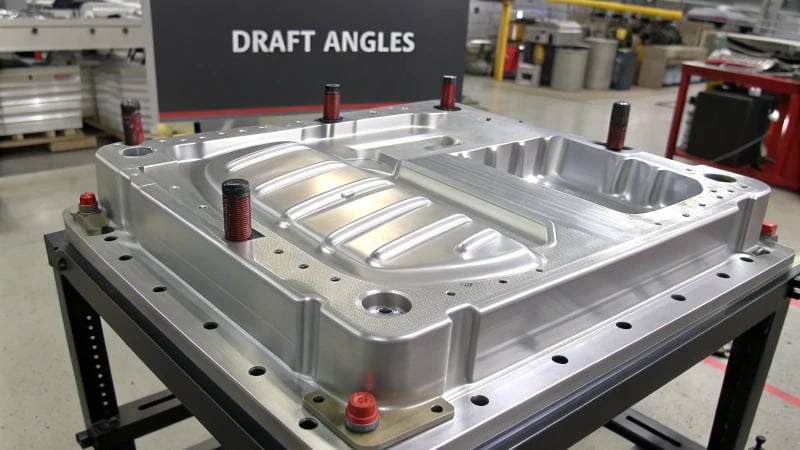
How Do Draft Angles Affect Mold Ejection?
Ever wonder how tiny details can make or break a design? Well, draft angles in mold design are just that crucial.
Draft angles facilitate smooth ejection of molded parts, minimizing sticking or damage, and thereby improving production efficiency and product quality..
The Importance of Draft Angles
You know, when I first started working in mold design, I didn’t fully grasp the importance of these seemingly small angles. But let me tell you, draft angles are like the unsung heroes in the plastic injection molding9 world. They’re essential because they help parts slide out of molds with ease. Without them, parts are more likely to get stuck and cause defects, and nobody wants that hassle.
How Draft Angles Work
Think of a draft angle as a gentle slope. This slight taper in the mold design is what reduces friction when ejecting a part. Imagine trying to slide down a hill versus a flat surface—it’s all about making things smoother and easier. Typically, these angles range between 1 to 3 degrees, depending on what you’re working with.
Impact on Production Efficiency
When I was new in the field, I quickly learned that draft angles don’t just prevent defects—they’re also your ticket to a more efficient production line. By lowering the resistance during ejection, they cut down on cycle times10, meaning less force and time are needed to pop out each part.
Practical Considerations for Designers
Designing molds feels a bit like solving a puzzle sometimes. Calculating the right draft angle is crucial to ensure the part’s integrity isn’t compromised. For instance, polypropylene often needs different angles than ABS due to shrinkage rates. Getting it wrong can be a costly mistake.
Table: Recommended Draft Angles by Material
| Material | Recommended Draft Angle |
|---|---|
| Polypropylene | 1-2 degrees |
| ABS | 2-3 degrees |
| Nylon | 3-5 degrees |
Industry Standards and Guidelines
Navigating industry standards is a bit like having a map when you’re lost—essential for successful mold design. Thankfully, there are plenty of guidelines on how to incorporate effective draft angles based on part geometry and material properties. They’ve been lifesavers in achieving optimal mold ejection results.
I always suggest checking out resources on mold design standards11 for detailed insights on applying draft angles effectively. It’s helped me refine my designs and could do wonders for yours too.
Draft angles reduce friction during mold ejection.True
Draft angles create a taper that minimizes friction, aiding ejection.
ABS requires a 5-degree draft angle for mold ejection.False
ABS typically requires a 2-3 degree draft angle for effective ejection.
What Role Does Part Symmetry Play in Designing Molds?
I remember the first time I truly understood the magic of symmetry in mold design—it was like unlocking a secret code. Suddenly, everything clicked, and I realized how this simple principle could transform the whole manufacturing process.
Part symmetry in mold design reduces complexity, minimizes errors, and enhances cost efficiency by ensuring balanced stress distribution. It improves the quality and durability of molded parts, making it essential for designers.
The Importance of Part Symmetry
In my experience, symmetry in mold design isn’t just about aesthetics—it’s like the backbone holding everything together. When a part is symmetrical, it experiences uniform forces during the molding process, which dramatically lowers the chance of warping or defects creeping in. I remember working on a project where we struggled with uneven pressure distribution, and it was a nightmare until we nailed the symmetry.
Benefits of Symmetrical Design
| Benefit | Description |
|---|---|
| Cost Efficiency | Simplifies mold fabrication, reducing production expenses. |
| Quality Improvement | Ensures consistent product quality with fewer errors. |
| Time-Saving | Streamlines the design process, shortening development time. |
Symmetry in Complex Mold Designs
Working on complex designs often feels like solving a puzzle, with symmetry being that one piece that holds the solution. I’ve found that using CAD software12 can be a game-changer here, helping to maintain that delicate balance needed for high-precision outcomes.
Designers often face tough calls about how much symmetry is necessary. While full symmetry is always the dream, partial symmetry still packs a punch in terms of balance and uniformity. It’s all about thinking ahead—considering how the part will be used and what manufacturing methods are at your disposal.
Case Study: Symmetry in Electronic Device Components
Think about designing plastic components for consumer electronics—a field I know all too well. Symmetrical parts not only fit better but also boost the product’s visual appeal, which is huge when you’re talking about something people use every day. Using injection molding techniques13, designers can exploit part symmetry to achieve high-volume production with minimal defects.
For instance, a symmetrical smartphone case ensures that each side experiences equal pressure during molding, reducing potential issues like warping or mismatching parts. This really drove home how critical symmetry is in maintaining both functionality and aesthetics.
Challenges and Considerations
But let’s not gloss over the challenges. Symmetry can sometimes feel like walking a tightrope between function and form. Designers have to weigh each project’s needs carefully to find that sweet spot.
Plus, as new materials or technologies come into play, they might demand a rethink of traditional symmetrical designs. I’ve learned that keeping an open mind and exploring innovative design tools14 can really pay off in overcoming these hurdles effectively.
Symmetrical molds reduce production costs.True
Symmetry simplifies mold fabrication, lowering production expenses.
Asymmetrical parts ensure uniform stress distribution.False
Only symmetrical parts experience uniform forces, reducing defects.
How Can Designers Optimize Molds for Complex Geometries?
Ever found yourself wrestling with the intricacies of mold design for those mind-bending geometries?
Designers can optimize molds for complex geometries by using advanced CAD software, topology optimization techniques, and innovative materials, enhancing precision and efficiency to meet high production standards.

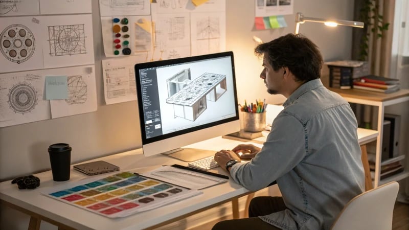
The Role of Advanced CAD Software
When I’m faced with intricate designs, leveraging advanced CAD software15 becomes my trusted ally. These tools, like SolidWorks and AutoCAD, offer high-precision modeling and simulation capabilities that allow me to visualize and solve potential problems before we even start cutting metal. Whether it’s addressing pesky undercuts or variable wall thicknesses, these software solutions help me stay ahead of the game.
Topology Optimization Techniques
Diving into topology optimization16 has been a game-changer for me. By tweaking material distribution within the design space, I can hit those performance targets while minimizing waste—something that’s crucial when working with complex geometries. It feels like a balancing act, ensuring structural integrity without overusing resources.
| Technique | Benefits |
|---|---|
| Topology Optimization | Reduces material waste, maintains structural integrity |
| Advanced CAD Tools | High precision modeling, pre-production issue detection |
Innovative Materials and Technologies
The thrill of choosing the right materials is like picking the perfect spice for a dish. Innovative materials17 such as high-performance polymers or metal alloys often find their way into my projects because they withstand the unique demands of our designs. Moreover, technologies like 3D printing and CNC machining open up fresh possibilities for prototype testing and mold creation.
Practical Design Tips for Mold Optimization
- Consider Undercuts: Planning with mold release in mind saves me from costly rework headaches.
- Wall Thickness: Keeping wall thickness uniform is my go-to strategy to prevent any warping or sinking disasters.
- Cooling Systems: Effective cooling channels are a must for reducing cycle times—trust me, they make all the difference.
Incorporating these strategies into my workflow has transformed not just how efficiently I work but also the quality of the molds I produce. By constantly exploring these avenues, I continue to push the boundaries of what’s possible in mold design. So let’s roll up our sleeves and dive into these techniques to see how they can elevate your next project!
Advanced CAD tools help detect mold design issues early.True
CAD tools simulate designs, identifying potential problems before production.
Uniform wall thickness increases risk of warping in molds.False
Uniform wall thickness actually helps prevent warping and sinking in molds.
Conclusion
Part geometry significantly impacts mold design in injection molding, influencing flow, cooling, and ejection efficiency. Understanding these factors is crucial for optimizing production and product quality.
-
Learn how optimizing material usage can reduce costs and improve efficiency in mold manufacturing. ↩
-
Discover why choosing the right core shape is essential for streamlined production. ↩
-
Explore how thorough analysis aids in achieving optimal mold design outcomes. ↩
-
Discover examples of undercut usage in automotive design for achieving specific aesthetics or functionalities. ↩
-
Explore how undercuts increase mold complexity with additional tooling requirements, potentially affecting cost and production efficiency. ↩
-
Uniform wall thickness helps in achieving consistent cooling, reducing warping and shrinkage issues in molded parts. ↩
-
Optimal wall thickness ensures adequate strength without compromising on material flow or aesthetic quality. ↩
-
CAD tools can identify potential weak points, helping designers optimize wall thickness for improved durability. ↩
-
Explore detailed steps of plastic injection molding to understand where draft angles play a role. ↩
-
Learn how optimizing draft angles can lead to reduced cycle times in manufacturing. ↩
-
Discover industry standards that guide the application of draft angles in mold design. ↩
-
Learn how CAD software supports maintaining symmetry in complex mold designs. ↩
-
Discover how injection molding efficiently produces symmetrical parts. ↩
-
Find out about new design tools that help overcome challenges in symmetrical mold design. ↩
-
Discover which CAD software offers features tailored to handling intricate mold geometries efficiently. ↩
-
Learn how topology optimization can streamline material usage while preserving design integrity. ↩
-
Find out about new materials that enhance mold durability and performance for complex designs. ↩