In the fast-paced realm of plastics manufacturing, density isn’t just a number; it’s the heart of product durability and performance. Let’s dive into how we can enhance it through mold optimization!
Mold optimization enhances the density of injection molded parts by refining mold design, improving manufacturing accuracy, and optimizing injection molding parameters such as pressure and temperature. This results in more uniform material distribution and superior part quality.
Continue reading to uncover detailed insights into mold design techniques, manufacturing precision enhancements, and process optimizations that can significantly elevate the density and quality of your injection molded parts.
Gate design impacts the density of molded parts.True
Proper gate design ensures uniform melt flow, enhancing part density.
What Role Does Gate Design Play in Mold Optimization?
Gate design is a critical component in mold optimization, directly influencing the density and quality of injection molded parts.
Gate design is pivotal in mold optimization as it determines the melt flow’s uniformity and efficiency during injection, impacting the final part’s density and structural integrity. Proper gate location and size are crucial for minimizing flow resistance and ensuring even material distribution.
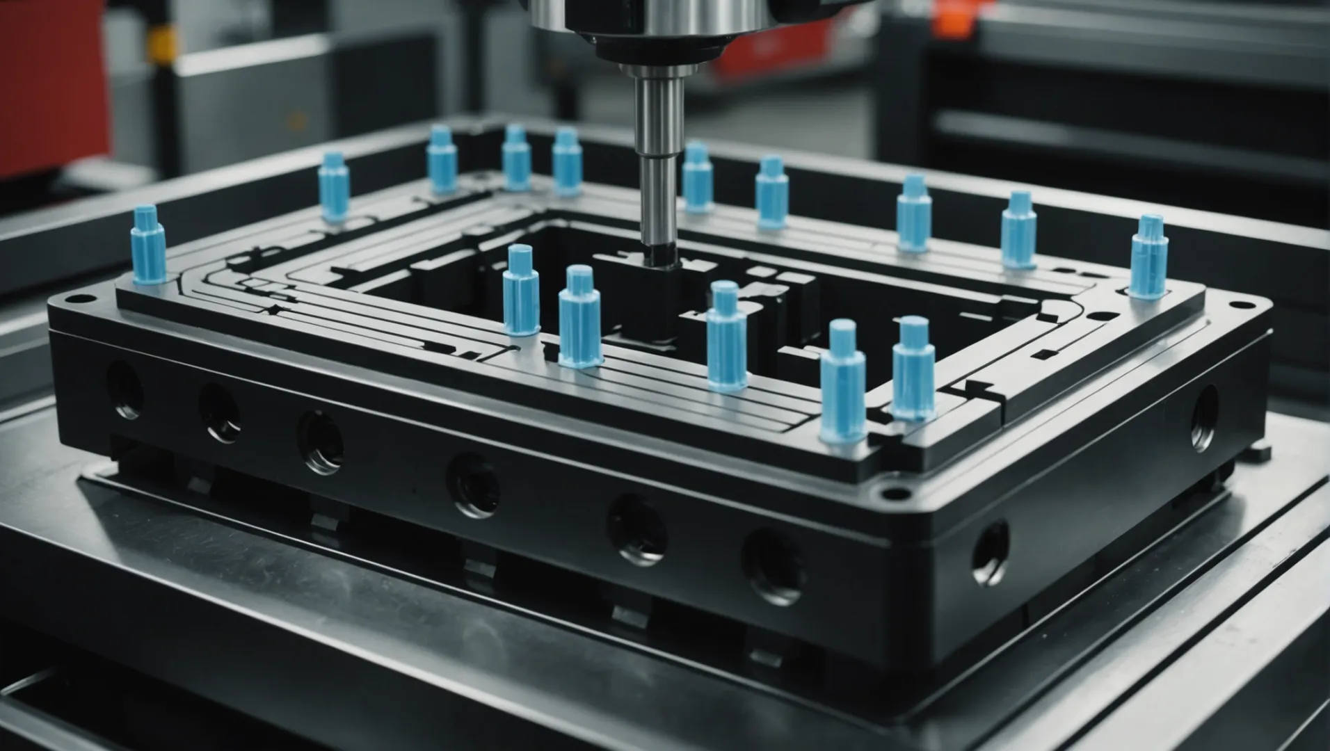
The Importance of Gate Location
Selecting an appropriate gate location is essential in ensuring uniform flow of the plastic melt. By placing the gate at thicker sections or key stress areas, you allow the plastic to fill more evenly, minimizing local density differences. For complex structures, utilizing multi-point gates or hot runner systems can further enhance melt distribution. These strategies prevent issues such as air traps or weld lines, which can compromise part integrity.
For instance, in automotive parts requiring high strength, strategically placed gates can significantly enhance durability by evenly distributing stress across the part. A well-chosen gate location not only improves mechanical properties but also reduces cycle time by optimizing the filling phase.
Optimizing Gate Size
The dimensions of the gate—its width, thickness, and length—play a crucial role in regulating melt flow. A gate that is too small increases flow resistance, leading to insufficient filling and reduced part density. Conversely, an overly large gate can cause issues like excessive flash or flow marks.
A balance must be struck; typically, the gate thickness should range between 50% to 80% of the wall thickness of the part. This range helps in achieving optimal flow without compromising the surface finish or structural properties.
Real-World Applications
In industries like consumer electronics, where precision is paramount, a finely tuned gate design ensures that parts meet stringent quality standards. Similarly, in medical devices, where material consistency is critical, effective gate design mitigates risks of defects that could lead to product failure.
Consider a case study involving multi-cavity molds1 for packaging applications. Here, a balanced gate design across cavities ensures each unit receives equal pressure and material distribution, leading to uniform density and reduced waste.
Tools and Technologies for Gate Design
Advancements in simulation software have revolutionized gate design. These tools allow engineers to model flow dynamics and assess various gate configurations before committing to production. Such technologies provide insights into potential issues like flow hesitation or jetting, enabling preemptive adjustments that save time and cost.
Moreover, hot runner systems2 have become increasingly popular for their efficiency in maintaining consistent melt temperature and reducing material waste. These systems often integrate with advanced temperature control units, offering precision that significantly enhances gate performance.
In conclusion, while gate design might seem a small part of the larger mold optimization process, its impact on part quality and manufacturing efficiency is profound. By understanding and leveraging the principles of effective gate design, manufacturers can produce superior injection molded parts with enhanced density and reduced defect rates.
Gate design affects the density of molded parts.True
Proper gate design ensures even melt distribution, affecting part density.
Hot runner systems increase material waste in molding.False
Hot runner systems reduce material waste by maintaining consistent melt flow.
How Can Runner Design Impact Part Density?
Runner design in injection molding plays a pivotal role in determining the density and quality of the final product.
Runner design affects part density by ensuring uniform melt flow and reducing pressure imbalances during injection molding. By optimizing the runner system, manufacturers can enhance material distribution, leading to denser and higher-quality parts.
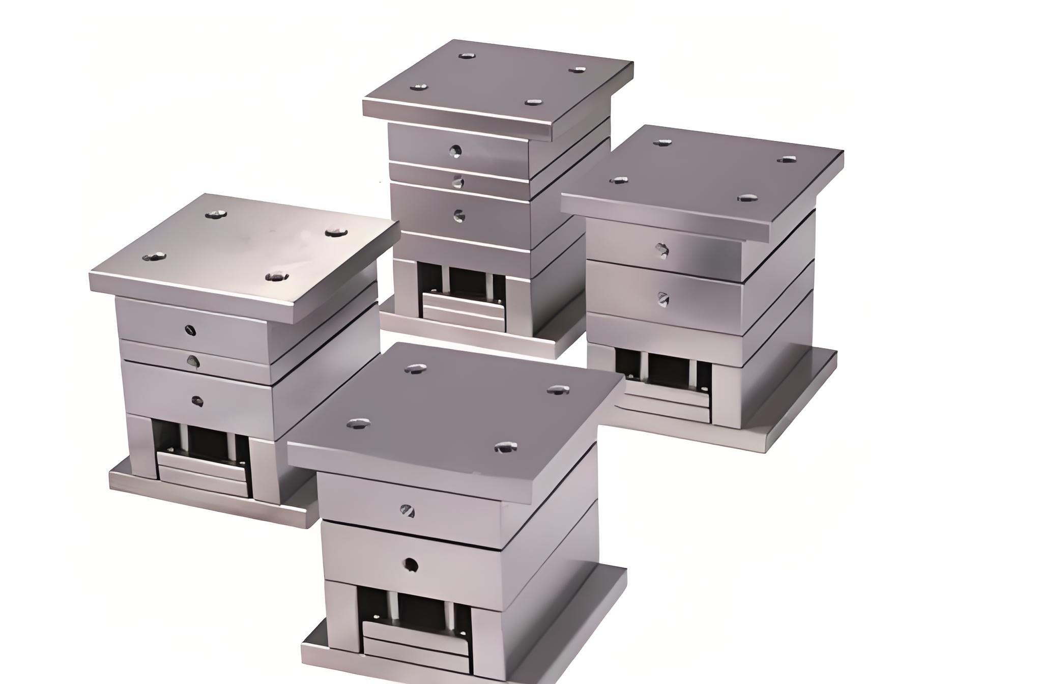
Understanding Runner Systems
The runner system in injection molding acts as a pathway that guides molten plastic from the injection unit to the cavities within the mold. The efficiency of this system directly influences the density of the finished part. A well-designed runner system ensures that molten plastic flows evenly and reaches each cavity with consistent pressure.
Balanced Runner Design
Implementing a balanced runner system3 is crucial for achieving uniform part density. In a balanced layout, the plastic melt flows through paths of equal length, ensuring that each cavity fills simultaneously and with the same pressure. This minimizes variations in density that can occur due to uneven pressure distribution.
Cross-Sectional Shape Optimization
Choosing the right cross-sectional shape for runners can significantly impact melt flow characteristics. For example:
- Circular runners: These offer minimal flow resistance, suitable for high-speed molding.
- Trapezoidal runners: They provide better heat dissipation, ideal for temperature-sensitive materials.
This table summarizes the impact of different runner shapes:
| Shape | Characteristics | Ideal For |
|---|---|---|
| Circular | Low flow resistance | High-speed injection molding |
| Trapezoidal | Enhanced heat dissipation | Temperature-sensitive materials |
Selecting an appropriate shape based on the material and molding speed can enhance part density by improving melt flow dynamics.
Symmetrical Runner Layout
A symmetrical runner layout4 ensures that each cavity receives molten plastic at the same rate and pressure. This approach eliminates discrepancies caused by runner imbalances, which can lead to areas of insufficient or excessive density in molded parts.
Material and Design Considerations
Finally, integrating material-specific design elements into runner systems can further improve part density. For instance, using advanced materials with better thermal properties can reduce cooling time discrepancies across cavities, contributing to uniform density throughout the part. Additionally, considering the thermal expansion coefficient of both the mold and material helps maintain consistent dimensions under varying temperatures.
In conclusion, optimizing runner design is a critical step in enhancing the density of injection molded parts, directly influencing their quality and performance.
Balanced runners ensure uniform part density.True
Balanced runners distribute melt evenly, ensuring uniform part density.
Circular runners provide better heat dissipation.False
Circular runners minimize flow resistance; trapezoidal ones dissipate heat.
Why Is Cavity Design Crucial for Density Enhancement?
Cavity design is a cornerstone of achieving high-density injection molded parts, impacting both precision and consistency.
Cavity design is critical for density enhancement because it directly affects the flow and cooling of the plastic melt, ensuring uniform distribution and minimal shrinkage. Optimizing cavity surface finish, wall thickness, and design features can significantly improve the density and quality of molded parts.
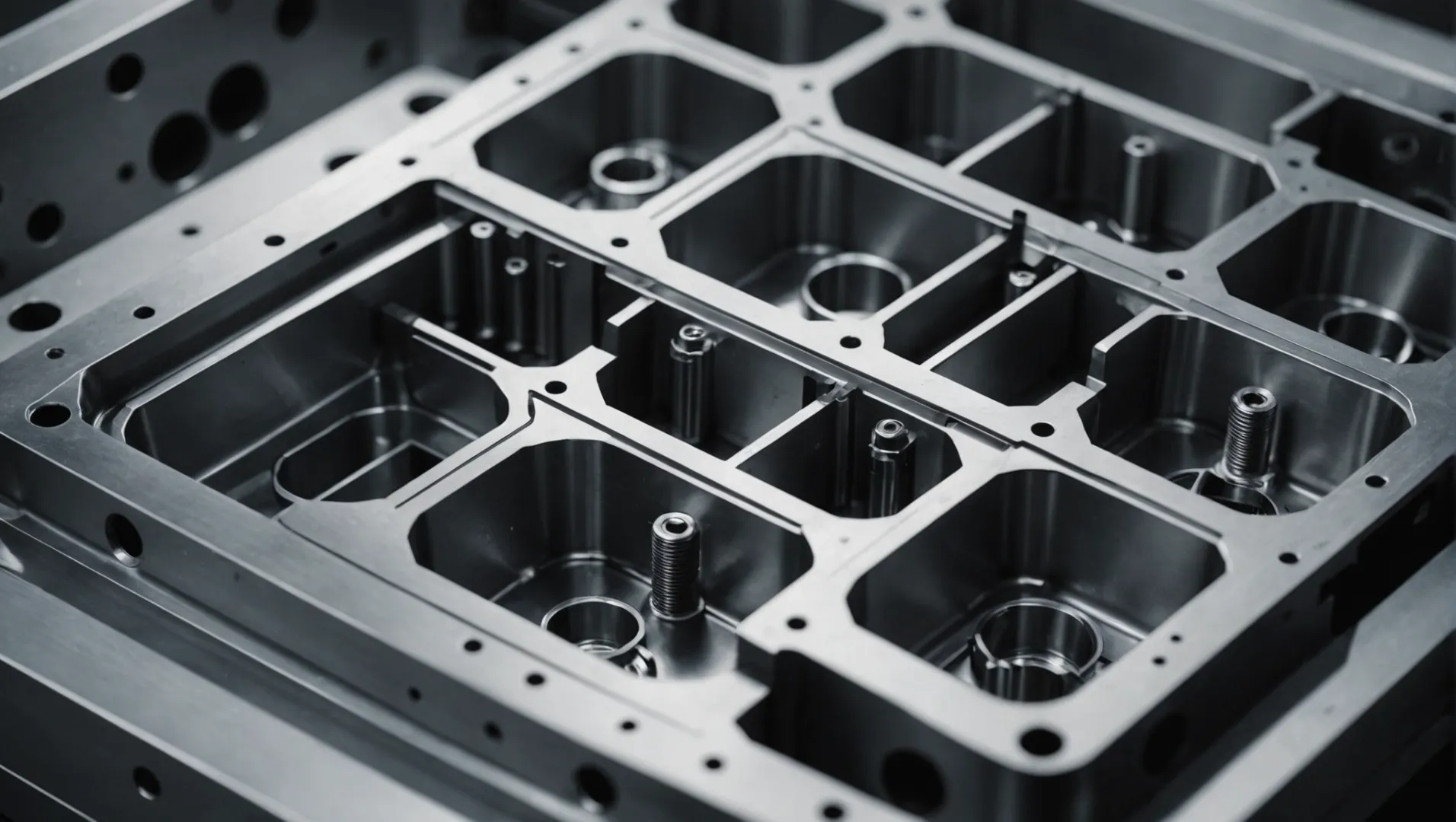
The Importance of Surface Finish
A key element in cavity design is the surface finish5 of the cavity itself. A smoother surface reduces flow resistance, allowing the plastic melt to fill the mold more uniformly. Techniques such as polishing and chrome plating are commonly used to enhance surface smoothness. Moreover, advanced coatings like DLC (diamond-like carbon) can further minimize friction, thereby increasing part density.
Optimal Cavity Wall Thickness
The wall thickness of the cavity plays a pivotal role in balancing strength and precision. Walls that are too thin may deform during the injection process, affecting both the dimensional accuracy and density of the parts. Conversely, overly thick walls can prolong cooling times and increase mold costs. Typically, maintaining a cavity wall thickness between 1.5 to 2 times the part’s wall thickness is recommended to ensure optimal density.
| Parameter | Impact on Density |
|---|---|
| Surface Finish | Reduces flow resistance, enhances uniformity |
| Wall Thickness | Balances strength, cooling time, and dimensionality |
Design Features and Their Influence
Strategic design features within the cavity can also impact density. Elements such as ribs and bosses should be carefully planned to support structural integrity without compromising material flow. Additionally, incorporating venting channels can prevent air traps that could cause uneven filling.
Ensuring Uniform Cooling
Uniform cooling is essential for minimizing shrinkage and warping in the final product. Designing a robust cooling system within the cavity layout helps maintain consistent temperature distribution throughout the part. Methods such as conformal cooling channels can significantly enhance cooling efficiency and contribute to a higher-density outcome.
Through meticulous attention to these aspects of cavity design, manufacturers can achieve injection molded parts with superior density and consistency.
Smooth cavity surface enhances plastic flow.True
A smoother surface reduces resistance, aiding uniform mold filling.
Thicker cavity walls always increase part density.False
Excessive thickness prolongs cooling, affecting precision and density.
What Injection Molding Parameters Should Be Optimized?
Optimizing injection molding parameters is crucial for enhancing the quality and density of the final product. The right adjustments can lead to stronger, more consistent parts.
Optimizing injection molding parameters involves adjusting pressure, speed, temperature, and cooling time to enhance part density and quality. These adjustments ensure uniform material distribution, reduce defects, and improve the mechanical properties of the final product.
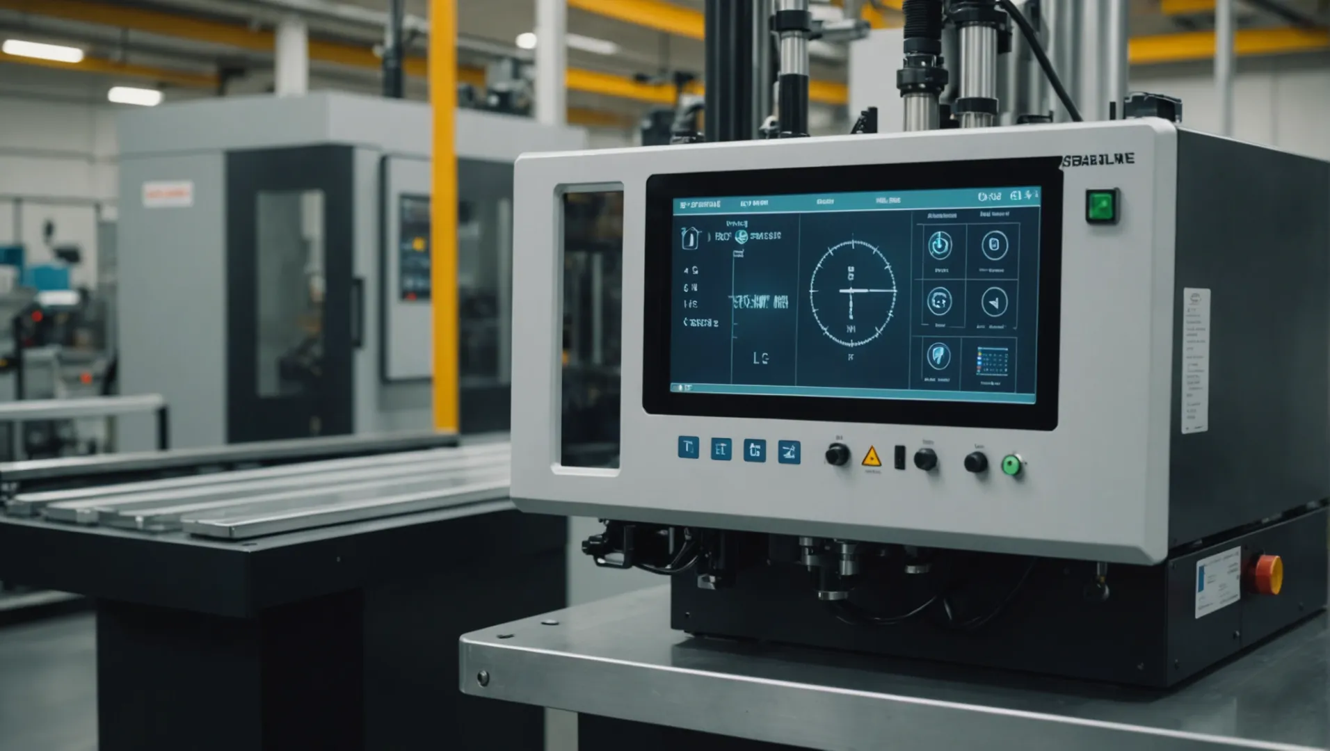
Pressure Optimization
Injection Pressure: Properly increasing injection pressure can ensure that the plastic melt fills the cavity tightly, enhancing the density of the part. However, excessive pressure may cause mold wear or internal stress, so it must be balanced appropriately. This involves analyzing factors such as material type and part thickness.
Holding Pressure: During the holding stage, maintaining a consistent pressure helps in compensating for material shrinkage. Properly timed holding pressure aids in improving the structural integrity and density of the part.
Speed Control
Injection Speed: A higher injection speed at the beginning can swiftly fill the cavity, while a slower speed towards the end prevents defects like flow marks. The key is to match the speed with material properties and part geometry for optimal results.
Temperature Management
Mold Temperature: Keeping the mold at an optimal temperature allows better flow of plastic melt, improving fill efficiency and density. Generally, the temperature should be near the glass transition point of the material used. Uniform mold temperature is crucial to avoid inconsistencies in part density.
| Parameter | Ideal Range | Impact on Part Density |
|---|---|---|
| Injection Pressure | Varies by material | Enhances fill quality |
| Injection Speed | High initial, low final | Controls flow marks |
| Mold Temperature | Near glass transition | Ensures uniform fill |
Cooling System Optimization
Cooling Time and Rate: Efficient cooling is vital to achieving uniform density across the part. Design a cooling system that allows even distribution of cooling channels to minimize deformation and enhance dimensional accuracy.
Advanced cooling techniques like conformal cooling channels6 can significantly improve cooling efficiency. This method adapts to complex part geometries for faster, more uniform cooling.
Water Flow Rate and Temperature: Maintain a controlled water flow rate and temperature to manage the cooling process effectively. Rapid yet uniform cooling improves overall part quality without compromising on density.
Injection pressure affects part density in molding.True
Proper injection pressure ensures tight cavity fill, enhancing density.
Higher mold temperature reduces fill efficiency.False
Optimal mold temperature improves flow and fill efficiency, not reduces it.
Conclusion
By embracing effective mold optimization strategies, we can significantly enhance part density, leading to improved quality and performance. Reflect on your current practices and consider these strategies to optimize your production.
-
Explore how multi-cavity molds optimize part density efficiently.: Multi-cavity or multi-cavity molds have at least two cavities and two cores, with a practical limit of hundreds of small cores and cavities. ↩
-
Discover how hot runner systems enhance gate performance.: Also, with hot runner systems, lower injection pressures can generally be used, which will reduce mold and platen deflection and keep flash … ↩
-
Learn how balanced runners ensure uniform part density.: BALANCING RUNNER SYSTEMS. Figure 1: Two naturally balanced (symmetric) runner systems and one counter-example. Figure 2: An artificially balanced runner system. ↩
-
Discover why symmetry in runners boosts part uniformity.: This ensures that the projected center of the cavities and runners align with the center of the clamping force of the injection machine. ↩
-
Discover how surface finish impacts material flow in molds.: All polish and texture is applied directly to the mold itself and transferred to the parts during the injection molding process. For this reason, secondary … ↩
-
Explore how conformal cooling channels enhance efficiency in complex mold designs.: By having the cooling channels closer to the part, you get more consistent cooling near the part’s surface and a higher quality plastic part. ↩

