Injection molding is a cornerstone of modern manufacturing, enabling the production of complex plastic parts with precision and efficiency.
Optimizing injection mold runner design involves key techniques such as runner size and layout optimization, gate design adjustments, material selection, temperature control, and leveraging flow analysis software. These strategies help improve part quality, reduce waste, and enhance production efficiency.
While understanding the basics provides an immediate advantage, delving deeper into each technique reveals nuances crucial for mastering injection molding. This comprehensive guide explores these strategies in detail, offering insights that go beyond the surface to ensure successful implementation.
Balanced runner layouts minimize defects in injection molding.True
Balanced layouts ensure uniform plastic distribution, reducing shrinkage and warping.
How Does Runner Size Affect Mold Performance?
The size of the runner in an injection mold significantly impacts both the efficiency and quality of molded parts.
Runner size affects mold performance by influencing plastic flow, cooling time, and material usage. An optimal runner size minimizes waste, ensures proper filling, and reduces defects. Balancing the diameter and length of both main and branch runners is essential for efficient molding and high-quality output.
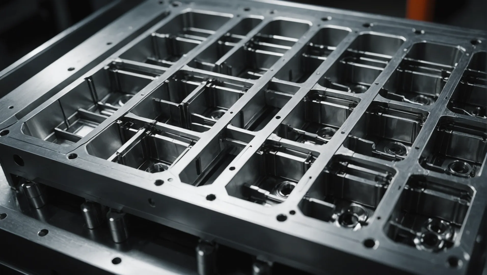
The Role of Main Runner Size in Mold Performance
The main runner1 acts as the primary conduit for molten plastic as it flows from the injection machine nozzle into the mold. The diameter and length of this runner directly influence material flow and cycle time:
- Diameter Considerations: A large diameter may seem beneficial for reducing flow resistance, but it can lead to excessive plastic use and longer cooling times. Conversely, a too-small diameter can hinder flow, causing incomplete filling and potential defects.
- Length Efficiency: Shorter main runners are preferred to minimize pressure and heat loss during plastic flow, improving overall efficiency.
Importance of Branch Runner Dimensions
Branch runners distribute the molten plastic into different cavities within the mold. The shape and size of these runners are crucial for balanced filling and avoiding defects:
- Cross-Sectional Shapes: Circular runners offer minimal flow resistance but are more challenging to process. In contrast, trapezoidal shapes balance ease of manufacture with effective flow characteristics.
- Size Ratios: Optimal width-to-depth ratios, typically between 2:3 and 3:4, ensure sufficient plastic flow while maintaining structural integrity.
Balancing Runner Layouts
In molds with multiple cavities, runner layouts must be carefully designed to ensure uniform filling:
- Balanced Layouts: These ensure that each cavity receives an equal amount of plastic simultaneously, reducing the risk of shrinkage marks and warping.
- Unbalanced Layouts: Sometimes necessary due to part design constraints, these require meticulous adjustments to runner dimensions and gate positions to achieve even filling.
Optimizing Through Flow Analysis Software
Using advanced flow analysis software2, engineers can simulate plastic flow through proposed runner designs, identifying potential inefficiencies or defects before physical mold production. This allows for:
- Predictive Adjustments: Making informed changes to runner size and layout based on simulated data.
- Enhanced Quality Control: Ensuring molds perform optimally under real-world conditions, reducing waste and improving part consistency.
Larger runner diameter increases cooling time.True
A larger diameter retains more heat, extending cooling duration.
Circular runners are easier to manufacture than trapezoidal ones.False
Circular shapes are harder to process compared to trapezoidal ones.
What Are the Benefits of a Balanced Runner Layout?
A balanced runner layout in injection molds ensures even filling across multiple cavities, enhancing product consistency and reducing defects.
A balanced runner layout ensures uniform distribution of molten plastic across mold cavities, minimizing defects like shrinkage and warping. This approach optimizes production efficiency and improves part quality by achieving consistent filling times and pressures.
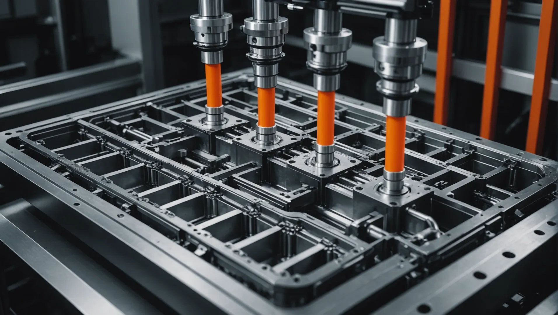
Understanding Balanced Runner Layouts
A balanced runner layout is crucial in multi-cavity injection molds. It ensures that each cavity receives an equal amount of molten plastic at the same time and pressure. This balance is achieved by designing the runner system such that the flow path from the injection point to each cavity is equal in length and cross-sectional area.
This design principle is essential because it minimizes common issues such as unbalanced filling, where some cavities might fill faster than others, leading to defects like shrinkage or warping. By ensuring that all cavities fill evenly, manufacturers can maintain high product consistency and quality.
Advantages of a Balanced Runner Layout
-
Consistency in Part Quality
By achieving uniform filling, a balanced runner layout reduces variations in part dimensions and appearance. This is particularly important for components requiring high precision and aesthetic appeal.
-
Reduced Defects
Common molding defects like shrinkage marks, warping, and sink marks are minimized with a balanced runner system. This happens because each cavity experiences the same filling dynamics, which reduces stress points and cooling inconsistencies.
-
Optimized Production Efficiency
A balanced layout often results in faster cycle times due to reduced pressure loss and efficient heat distribution across the mold. This efficiency not only speeds up production but also reduces energy consumption.
-
Material Savings
By minimizing waste and rework due to defective parts, a balanced runner system contributes to significant material savings over time.
Designing a Balanced Runner Layout
Designing an effective balanced runner layout involves several considerations:
- Length and Diameter of Runners: Ensure equal lengths from the injection point to each cavity. The diameter should be optimized to maintain adequate flow without excessive material usage.
- Cross-Sectional Shape: Circular cross-sections provide the least flow resistance but may be harder to machine compared to trapezoidal shapes. Consider trade-offs between ease of manufacturing and performance.
- Flow Analysis Tools: Utilize flow analysis software3 to simulate and verify the effectiveness of your runner design before production. This software helps predict flow patterns and identify potential issues.
By focusing on these aspects, manufacturers can effectively implement a balanced runner layout, leading to enhanced product quality and operational efficiency.
Balanced runner layout reduces shrinkage in molds.True
It ensures uniform filling, minimizing defects like shrinkage.
Unbalanced runner layouts improve product consistency.False
Unbalanced layouts cause uneven filling, leading to inconsistencies.
How to Choose the Right Gate Type for Your Mold?
Selecting the ideal gate type is crucial for ensuring optimal plastic part production in injection molding.
To choose the right gate type for your mold, consider the shape, size, wall thickness, appearance requirements, and production batch of the plastic part. Different gate types, such as direct, side, point, and latent gates, offer unique advantages tailored to specific injection molding processes.
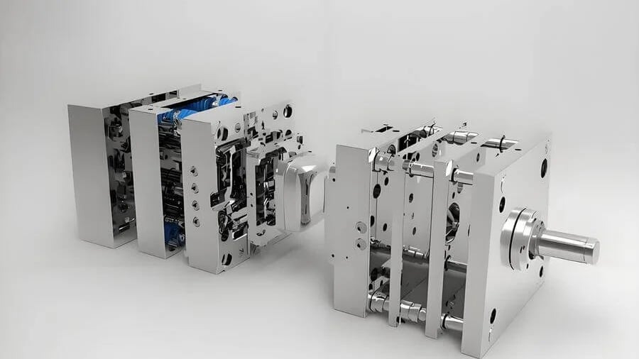
Understanding Different Gate Types
Choosing the right gate type is essential to optimize the injection molding process4. Each gate type caters to different part characteristics and production requirements:
-
Direct Gate: Best for single-cavity and deep-cavity parts. It facilitates easy flow but may leave marks that need post-processing.
-
Side Gate: Suitable for small to medium parts. This gate minimizes post-molding marks, enhancing surface finish.
-
Point Gate: Ideal for high-appearance requirements. It offers precise control but may increase complexity.
-
Latent Gate: Perfect for automated production. It’s hidden within the part, reducing cosmetic issues but requires careful design.
Factors Influencing Gate Selection
Several factors influence gate selection, including part dimensions, wall thickness, and appearance standards:
-
Shape and Size: Larger parts may require more robust gates like direct gates to ensure complete filling.
-
Wall Thickness: Thicker walls support higher pressure, enabling the use of smaller gates without compromising flow.
-
Appearance Requirements: Parts with stringent aesthetic standards benefit from point or latent gates to hide gate marks.
-
Production Volume: For large batches, selecting a gate that minimizes cycle time without sacrificing quality is critical.
Utilizing Flow Analysis for Gate Design
Using flow analysis software helps in determining the optimal gate placement and size. This tool predicts flow patterns and potential defects, offering data-driven insights:
| Software | Key Features |
|---|---|
| Moldflow | Simulates flow dynamics and identifies weak spots |
| Sigmasoft | Provides detailed thermal analysis for improved accuracy |
Balancing Layout and Gate Design
A balanced runner layout enhances gate performance by ensuring uniform cavity filling. While direct gates may suffice in straightforward designs, complex molds might benefit from multiple gates strategically placed to minimize pressure differences and prevent defects like shrinkage or warping. Adjusting the gate size and position can further refine this balance, enhancing overall mold performance and efficiency.
Direct gates are best for single-cavity parts.True
Direct gates facilitate easy flow, ideal for single-cavity molds.
Point gates are unsuitable for high-appearance parts.False
Point gates are ideal for parts with high-appearance requirements.
Why Is Temperature Control Critical in Runner Design?
Temperature control in runner design is pivotal for ensuring optimal flow and quality of injected plastic parts.
Temperature control in runner design affects plastic flow, filling precision, and part quality. Precise temperature management minimizes defects, optimizes flow, and enhances the final product’s structural integrity.

The Importance of Temperature in Runner Design
Temperature plays a crucial role in the runner system of an injection mold. It directly impacts the viscosity of the plastic melt, which in turn affects the flow rate and filling precision. An optimally controlled temperature ensures that the plastic maintains its fluidity, reducing the risk of defects such as warping or incomplete filling.
Methods for Temperature Control
To achieve effective temperature regulation, various methods can be employed:
- Heating Elements: These include electric heating rods or heating rings that maintain the runner’s temperature above the melting point of the plastic. This setup is essential for high-temperature plastics to ensure smooth flow and filling.
- Cooling Channels: Implementing cooling water channels within the runner helps dissipate excess heat. Designs like straight-through or wrap-around types are commonly used to maintain consistent temperatures and prevent overheating.
Balancing Heat and Flow
A delicate balance between heating and cooling is necessary to optimize runner performance. If the runner is too hot, it can lead to degradation of the plastic material. Conversely, if it’s too cool, it may cause premature solidification, leading to blockages and inconsistent part quality. Utilizing flow analysis software5 can predict temperature distribution and help design an efficient thermal management system.
Material Selection’s Role in Temperature Control
The choice of material for runners also influences thermal management. Materials like copper alloys or aluminum provide excellent thermal conductivity, allowing for rapid heat dissipation. For molds dealing with high-temperature or corrosive plastics, selecting materials with enhanced thermal properties is vital to improve durability and performance.
By understanding these components and their interplay within the runner system, manufacturers can significantly enhance part quality, reduce waste, and achieve higher efficiency in production.
Temperature affects plastic flow in runner design.True
Temperature changes plastic viscosity, impacting flow rate and quality.
Copper alloys are poor thermal conductors in runners.False
Copper alloys have high thermal conductivity, aiding heat dissipation.
Conclusion
By integrating these techniques, manufacturers can significantly enhance their injection molding processes, achieving higher quality outputs with reduced costs and improved efficiency.
-
Learn why main runner size is crucial for efficient mold performance.: Properly sizing the gate and runners in a feed system is critical to reducing processing requirements, increasing manufacturability, and reducing part cost. … ↩
-
Discover how flow analysis software enhances mold design and efficiency.: With the power of Moldex3D Flow, you can clearly observe melt flow behavior, accurately detect potential weldline and detect short shot, air trap problems, etc. ↩
-
Discover how flow analysis software enhances mold design efficiency.: Mold flow analysis (MFA) software simulates the flow of plastic, which allows you to elevate part and mold design to create products of impeccable quality. ↩
-
Explore diverse gate types and their unique benefits in injection molding.: Edge gates do not require a specific resin wither type, making them an ideal choice if you can simplify your design for injection molding. ↩
-
Discover how software predicts temperature distribution for better runner designs.: Mold flow analysis is a software-based simulation that predicts how a plastic resin will flow into and fill an injection mold. It also accounts for part cooling … ↩

