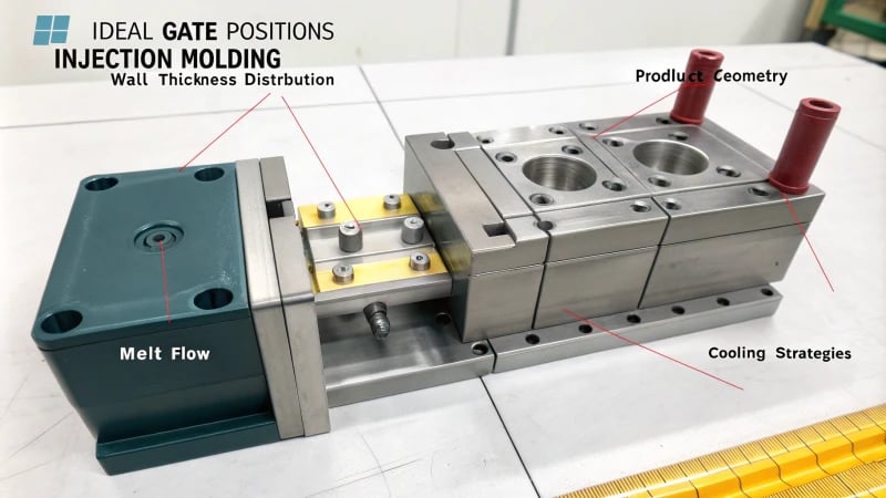
Looked at an item and wondered, "Shrinkage marks? Again?" Trust me, I have experienced it too.
To fix shrinkage marks, designers place gates in the right spot during injection molding. Correct gate placement helps spread melt evenly and cool it smoothly. Wall thickness and shape matter a lot. Better cooling means fewer defects. Fewer defects matter.
I remember my first days in design when I encountered those annoying shrinkage marks. It was like chasing something you couldn’t see – a tough and annoying experience. I slowly grasped that getting the gate’s position right is just the beginning. The real challenge lies in balancing gate location, wall thickness and the whole product’s shape.
I had a project with a plastic cup and a handle, which turned into my personal puzzle. Putting the gate near the thicker handle part was key. This allowed the plastic to flow back as it cooled, reducing shrinkage marks. The client was very satisfied. Let me share more stories to help you improve your methods.
Gate at geometric center ensures uniform melt flow.True
Placing the gate at the center allows symmetrical melt distribution.
Long melt flow paths reduce pressure loss in injection molding.False
Long paths increase pressure loss, hindering melt replenishment.
Why Does Gate Position Matter in Injection Molding?
Picture the excitement of creating an ideal product, only to discover that even the smallest detail might ruin or complete your masterpiece.
Gate position in injection molding is crucial. It directs how molten plastic travels through the mold. Correct placement helps avoid flaws. It also achieves even filling and decreases pressure loss, especially in models with different wall thicknesses.

Combined Design of Gate Position and Wall Thickness
I worked on designing a simple round plastic dinner plate. It seems easy, but gate position1 was tricky. Uniform wall thickness taught me the importance of center gate placement. This helped the molten plastic spread evenly, avoiding those annoying shrinkage marks. Imagine a ripple on a pond – perfectly even, filling each part just right.
For uneven wall thickness products like a plastic cup with a handle, uneven wall thickness was a problem. This time, I placed the gate near the thick handle. The handle cooled slower and needed more melt to avoid voids. Like filling a cup with water – careful and balanced.
| Aspect | Strategy |
|---|---|
| Uniform Thickness | Centered Gate |
| Uneven Thickness | Gate near Thick Part |
Avoiding Pressure Loss
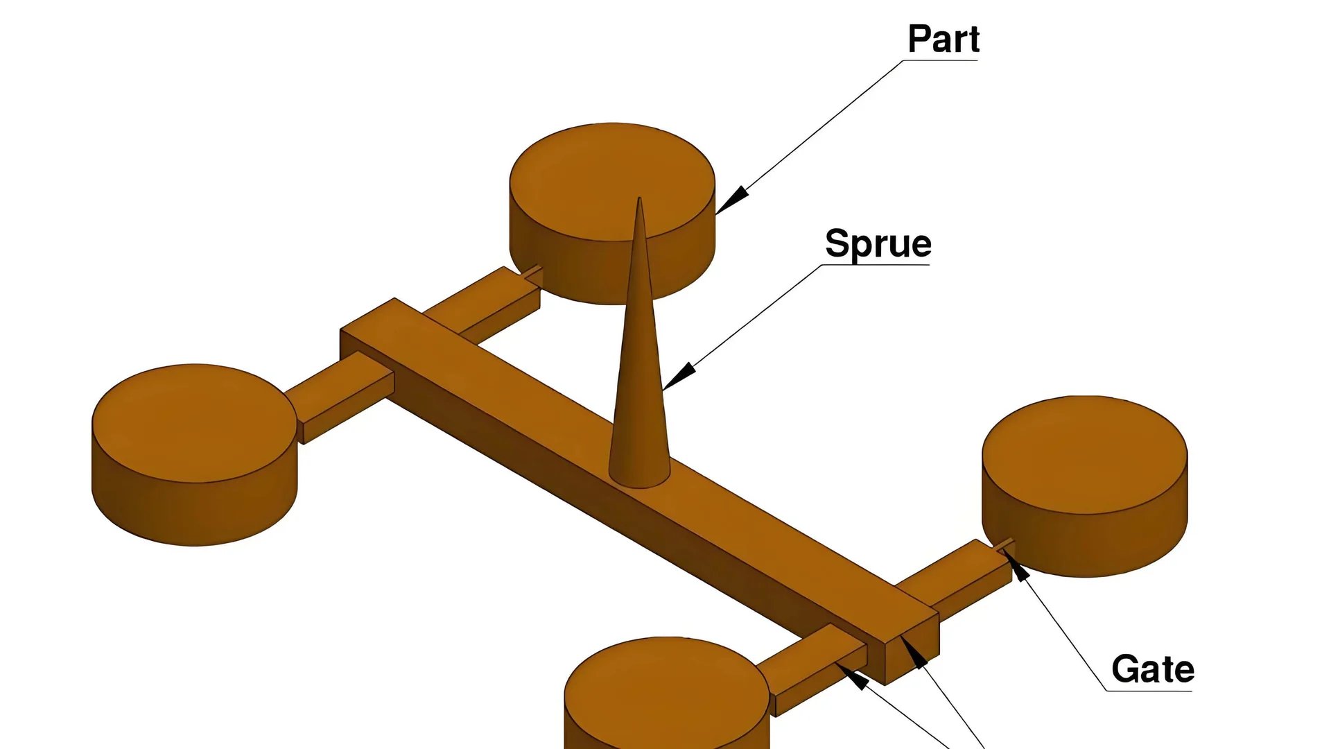
Complex shapes brought other challenges. I worked on a design with multiple branches. Keeping the melt flow path short mattered because long paths caused pressure loss and incomplete fills. So, I placed several gates strategically, like setting up a train track with perfect curves keeping speed.
For complex shapes with multiple branches:
- Multiple gates or strategically placed single gates help reduce pressure loss at branch ends.
Weld Mark Position Considerations
Weld marks also posed a problem, especially in thick spots where they weakened the structure there. I adjusted gate positions to move these marks—think of it like redirecting traffic to avoid jams. I guided the melt flow to make weld marks appear in less noticeable places, like the edge of a big shell.
Strategically placing gates can drastically improve product quality by addressing these aspects effectively. If you face similar design challenges, more insights on injection molding optimization2 might really help you.
Gate position affects pressure loss in molding.True
Gate placement impacts melt flow path length, influencing pressure loss.
Weld marks do not affect shrinkage marks.False
Weld marks in thick areas can increase shrinkage due to weak strength.
How Does Wall Thickness Affect Gate Placement?
Do you ever wonder why small marks or flaws appear on plastic things? Their location usually depends on how the gates in the molding machine are positioned.
Wall thickness changes where gates are placed. It guides the flow of liquid plastic and pressure. Even thickness places gates in the center. Uneven thickness places gates closer to thicker areas for better quality.

Importance of Wall Thickness in Gate Placement
I remember the first challenge of placing a gate. It felt like playing a game, where every step mattered to avoid costly errors. Placing the gate at the geometric center is essential when designing with even wall thickness. Imagine a simple dinner plate. By putting the gate in the middle, the melt flows evenly, preventing annoying shrinkage marks.
However, sometimes things aren’t symmetrical. Consider a plastic cup with a handle. The handle is usually thicker, so the gate should be nearer to it. This careful spot helps the handle cool with enough material, avoiding gaps from shrinkage.
| Design Aspect | Uniform Thickness | Uneven Thickness |
|---|---|---|
| Gate Position | Geometric Center | Near Thick Section |
| Melt Flow Path | Symmetrical and Centralized | Close to Thickest Part |
Minimizing Pressure Loss
Gate placement is like threading a needle. A long flow path might lose pressure. I learned early in mold design that shorter distances improve results. Complex shapes, like multi-branched parts, may need several gates. Imagine watering plants at the far ends of your garden; without enough hoses or water pressure, some plants remain dry.
For complex shapes3, multiple gates or strategic positioning ensures uniform melt distribution.
Managing Weld Marks
Weld marks bothered my designs like an unwelcome shadow. Wrong placement worsens shrinkage, especially in thick spots. Proper gate placement guides these marks to less critical areas. I often adjust the gate positions4 and injection order in large plastic shells. This way, weld marks appear on hidden parts, keeping both look and functionality.
Gate should be at geometric center for uniform thickness.True
Placing the gate at the center ensures even melt distribution.
Long melt flow paths reduce pressure loss in cavities.False
Long paths increase pressure loss, hindering proper melt filling.
Why Is Minimizing Melt Flow Path Crucial?
The flow path in injection molding is very important. A short path often impacts the process greatly.
Shorter melt pathways are critical. They lower pressure loss and improve melt spread. This action helps avoid defects such as shrinkage marks and weld lines. Correct gate positioning guarantees evenness and high quality. These are key to efficient mold creation. Efficient mold creation is really important.

The Effect of Melt Flow Path on Pressure Drop
Long ago, as a beginner mold designer, an important lesson taught me much. A complicated mold project gave many difficulties. I could not understand the reason for so many flaws in the finished piece. Investigating further, I found the melt flow path was too lengthy. It felt like expecting a marathon runner to sprint – pressure drop was certain, causing thicker walls to show unwanted shrinkage marks.
Here’s the truth: a long melt flow path greatly lowers pressure during filling. Thicker areas do not receive enough melt, leading to problems. Positioning gates to reduce distance keeps pressure consistent and improves quality.
| Factors | Impact |
|---|---|
| Long Flow Path | High Pressure Loss |
| Short Flow Path | Low Pressure Loss |
Gate Location and Wall Thickness
Gate location plays a critical role. It should be precise for smooth flow. For items with uniform wall thickness, placing the gate at the center evenly spreads the melt. A round plate design test showed central gates resolve unwanted shrinkage.
In a different case, uneven thickness needs more thought. Thicker spots cool slowly, needing gates close by. Think of a plastic cup with a thick handle – the gate must sit near to fill well during cooling.
Stopping Weld Marks in Vital Areas
Weld marks are like unwanted visitors; they disturb and can increase shrinkage, especially in thick parts. Correctly placing gates guides these marks to less important places, like edges. Using multiple gates or changing injection order probably helps fill thick sections, reducing defects.
Understanding Weld Marks5 is very essential for good looks and strength.
Being careful with these mold design details improves product quality a lot while reducing costs. This focus leads to a more dependable and smooth production process.
Gate should be at the geometric center for uniform wall thickness.True
Central gate placement ensures symmetrical melt flow, reducing shrinkage.
Long melt flow paths increase pressure loss and cause shrinkage marks.True
Extended paths lead to pressure drop, hindering melt replenishment in thick areas.
How do weld marks interact with gate design?
Weld marks often spoil a perfectly molded piece. These lines are more than just a visual problem; they reveal the connection between gate design and melt flow.
Weld marks appear at points where different flows of melted material converge in injection molding. A clever gate layout considers wall thickness and paths of melt flow. This setup reduces these marks by controlling how the material fills and cools.

Understanding Weld Marks
When I joined the world of injection molding, weld marks were like mysterious stains that suddenly appear on your favorite shirt – unexpected and annoying. These marks show up where two or more flow fronts meet during the injection molding6 process. They may seem just like lines, but they often weaken a part, much like one loose stitch can make a sweater fall apart.
Gate Position and Wall Thickness
For products with uniform wall thickness, centering the gates becomes very important. Imagine pouring pancake batter on a griddle; you want it to spread evenly. Similarly, placing the gate in the center of something like a round plate ensures the melt spreads evenly, avoiding ugly shrinkage marks.
In contrast, with uneven wall thickness, the task becomes really difficult. Think of a plastic cup with a handle. The handle is thicker and cools slower, needing extra melt to stay strong. Here, gates belong near these thick sections, just like properly watering plants in a garden.
| Wall Thickness | Recommended Gate Placement |
|---|---|
| Uniform | Center of product |
| Uneven | Near thick sections |
Avoiding Pressure Loss
Long melt flow paths create issues, similar to using a hose with a kink to water a garden. To cut down pressure loss, gates need careful placement. Complex shapes might require many gates for even melt spread. It is like giving each tree branch its own water source – every part needs enough nourishment.
For instance, parts with branches need gates positioned to feed each branch swiftly, reducing pressure loss at the branch ends.
Weld Marks and Gate Position
Weld marks in thick parts are a designer’s problem – like trying to patch a hole in a beloved sweater. Gates should steer weld marks to less critical thin-walled areas. Moving gate positions in a large plastic shell can shift weld marks to the edges, keeping them hidden while making sure thick sections fill properly.
Learning about these things, I found that better gate design cuts down weld marks and also raises product quality. It’s about the careful balance between melt flow and cooling – get it right and you really create something great.
Gate position affects weld mark location.True
Gate design influences where weld marks appear, impacting aesthetics.
Thick walls should have gates far from them.False
Gates should be close to thick walls for better melt replenishment.
Conclusion
Proper gate positioning in injection molding is crucial to prevent shrinkage marks by ensuring even melt flow and minimizing pressure loss, especially in products with varying wall thickness.
-
This link provides detailed insights into how gate position affects mold quality, essential for designers like Jacky. ↩
-
Learn advanced methods to optimize injection molding processes for better product quality and efficiency. ↩
-
Discover methods to strategically place gates in complex molds for balanced melt distribution. ↩
-
Learn about techniques for controlling weld mark positions to improve product aesthetics and functionality. ↩
-
Discovering methods to minimize weld lines can enhance the visual and structural quality of molded products. ↩
-
This link provides a detailed explanation of weld line formation, crucial for understanding their impact on gate design. ↩


