Injection mold runner design is a game-changer in manufacturing.
Common mistakes in injection mold runner design include improper runner size and shape, incorrect gate positioning, and unbalanced runner systems. By addressing these issues through careful design and mold flow analysis, you can improve product quality and reduce costs.
Understanding the mistakes is just the beginning; let’s explore how we can rectify these issues effectively!
Improper runner size leads to increased defects.True
Runner size affects melt flow and cooling, impacting quality.
How Does Runner Size Affect Product Quality?
Runner size in injection molds is crucial for ensuring high-quality products. Incorrect sizing can lead to defects and inefficiencies.
Runner size affects product quality by influencing melt flow, cooling rates, and stress distribution. Optimal sizing ensures efficient filling, reduces material waste, and minimizes defects such as warping or cracking.

Understanding the Role of Runner Size
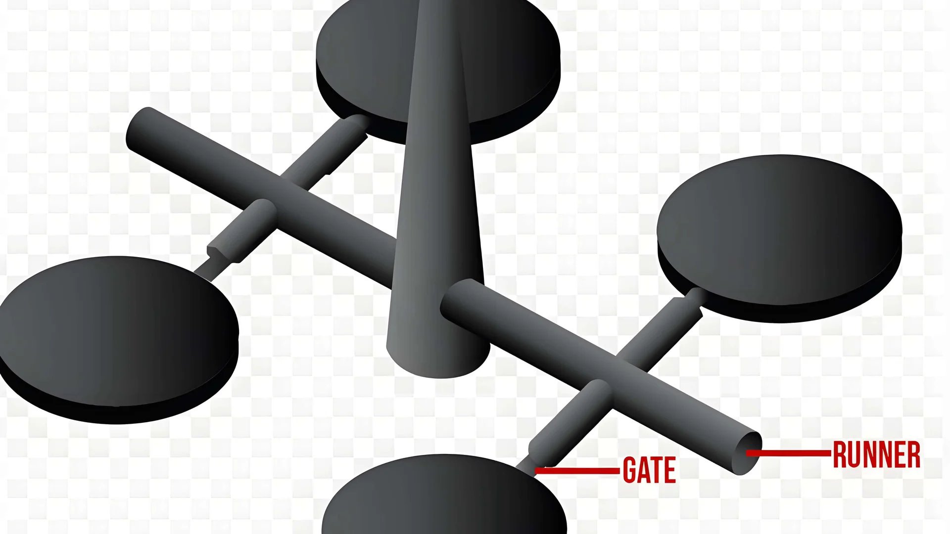
The runner system in injection molding acts as the pathway for molten plastic to travel from the injection unit to the mold cavity. The size of the runner directly affects how efficiently and uniformly the plastic fills the mold. An unreasonably sized runner1 can lead to several problems that impact product quality.
-
Too Thick Runners: If a runner is excessively thick, the plastic melt will remain longer in the runner. This prolonged residence time can lead to excessive cooling or even thermal degradation of the material before it reaches the cavity. For instance, when manufacturing small thin-walled items, an overly thick runner can cause incomplete filling, resulting in material shortages and defects.
-
Too Thin Runners: Conversely, runners that are too thin increase the flow resistance of the melt. This requires higher injection pressure, leading to increased energy consumption and potential wear on machinery. Additionally, thin runners can cause internal stress, leading to defects like warping or cracking. An example is when thin runners cause excessive shearing, leading to overheating, decomposition, and defects such as bubbles or silver streaks in the product.
Strategies for Optimal Runner Sizing
To optimize runner size, it is essential to consider factors like product dimensions, shape, and wall thickness. Generally, the runner diameter should be between 1.5 to 2 times the product’s wall thickness. For larger or thicker products, a larger runner may be necessary, while smaller or thinner products benefit from a reduced runner size.
Employing mold flow analysis software can assist in simulating different runner size scenarios to determine the optimal design. This approach not only enhances product quality but also reduces material wastage and production costs.
Case Study: Runner Size Adjustment
Consider a scenario where a company faced issues with warping in their injection-molded parts. By analyzing their runner system, they found the runners were too thin, causing uneven filling and stress distribution. By adjusting the runner size according to expert recommendations2, they achieved more consistent filling, reduced stress, and improved overall product quality.
Through thoughtful runner design and analysis, manufacturers can significantly enhance their product’s performance and reliability. Ensuring the runner size aligns with the product’s specific requirements is a vital step towards achieving optimal manufacturing outcomes.
Thick runners reduce material degradation risk.False
Thick runners can cause excessive cooling, leading to degradation.
Thin runners increase injection pressure needs.True
Thin runners increase flow resistance, needing higher pressure.
What Are the Best Practices for Designing Flow Channel Shapes?
Flow channel shape design is crucial in molding, affecting both the efficiency and quality of the final product.
Best practices for designing flow channel shapes include using arc transitions at corners and ensuring regular cross-sectional shapes to facilitate smooth and uniform melt flow.

Importance of Flow Channel Shape
Designing the shape of a flow channel can greatly influence the efficiency of the injection molding process. Flow channel shapes affect how the molten plastic travels through the mold, influencing factors like pressure, temperature, and flow uniformity. A well-designed flow channel minimizes defects such as warping, air bubbles, and weld lines.
Common Errors and Solutions
Sharp Corners and Their Impact
Sharp corners within flow channels can lead to increased shear stress on the molten material. This can result in higher temperatures, causing the plastic to decompose and create unwanted defects like bubbles or silver streaks.
- Solution: Implement arc transitions3 to reduce shear stress. The radius of these arcs should typically be between 0.25 to 0.5 times the runner diameter.
Irregular Cross-Sectional Shapes
An irregular cross-section can cause uneven flow speeds, leading to defects such as local thickness variations and weld marks.
- Solution: Aim for circular or trapezoidal cross-sections to promote a uniform flow rate throughout the runner system. This consistency helps maintain a smooth transition of the melt.
Mold Flow Analysis
Utilizing mold flow analysis software allows designers to simulate different flow channel configurations. By adjusting parameters such as shape, size, and arc radius, it’s possible to identify the optimal setup that minimizes material waste while maintaining product integrity.
- Example: In large-scale productions, simulations can reveal how small adjustments in channel shape can significantly impact the overall efficiency and quality of the output.
Materials Consideration
The properties of the plastic material being used are also a critical factor in determining the best flow channel shape. Different materials may require unique channel designs to optimize their flow characteristics without compromising the product quality.
- Consideration: Some plastics might need smoother transitions due to their viscosity and thermal sensitivity.
Conclusion
By incorporating these best practices—such as utilizing arc transitions and maintaining regular cross-sectional shapes—manufacturers can enhance the performance of their injection molds. Furthermore, leveraging mold flow analysis allows for precise customization tailored to specific production needs. This not only improves product quality but also reduces costs by minimizing defects and material waste.
Arc transitions reduce shear stress in flow channels.True
Arc transitions smooth out sharp corners, reducing stress and defects.
Irregular cross-sections promote uniform melt flow.False
Irregular shapes cause uneven flow, leading to defects like weld marks.
Why Is Gate Position Critical in Runner Design?
The gate position in runner design is vital, influencing the flow, quality, and efficiency of injection molding processes.
The criticality of gate position in runner design stems from its direct impact on the filling pattern, product quality, and production efficiency. Proper gate positioning ensures uniform cavity filling, minimizes stress concentration, and reduces defects, leading to higher-quality products and optimized manufacturing.

Impact on Filling Pattern
The location of the gate determines how the molten material fills the cavity. A strategically placed gate ensures a uniform filling pattern, which is essential for maintaining consistent product quality. By placing the gate at a thicker section of the product or at a central location, manufacturers can achieve more even distribution of material. This approach helps in minimizing defects such as weld lines and air traps.
For example, if the gate is positioned at a thinner section of the mold, there is a risk of incomplete filling or uneven pressure distribution. This can lead to stress concentrations, which might cause warping or cracking under load.
Influence on Product Quality
Gate positioning plays a crucial role in defining the mechanical properties and surface finish of the molded product. A poorly positioned gate can result in excessive shear stress on the material, leading to degradation and defects like discoloration or brittleness.
Using mold flow analysis software4, designers can simulate different gate positions to evaluate their impact on the final product. This tool helps in predicting potential issues like material shortages or over-packing, allowing for adjustments before actual production begins.
Production Efficiency Considerations
The efficiency of the injection molding process is significantly influenced by gate placement. Optimal gate positioning reduces cycle time by ensuring quicker and more efficient filling, thus saving energy and resources. Moreover, it minimizes post-processing requirements by reducing flash and other unwanted artifacts.
For instance, a centrally located gate can lead to a balanced filling of multi-cavity molds, preventing discrepancies in product weight and dimensions. It also facilitates easier ejection of parts, improving overall production throughput.
To sum up, assessing gate position through comprehensive analysis5 is not just about enhancing product quality but also about optimizing the entire manufacturing process. Proper design considerations ensure that each element of the runner system works harmoniously towards efficient production.
Gate position affects injection molding quality.True
Gate position influences filling patterns, stress distribution, and defects.
Centrally located gates lead to uneven filling.False
Centrally located gates ensure balanced filling and reduce defects.
How Can You Achieve Runner Balance in Multi-Cavity Molds?
Balancing runners in multi-cavity molds is crucial to ensure uniform product quality and efficient manufacturing processes.
Achieving runner balance in multi-cavity molds involves designing consistent runner lengths, shapes, and sizes across all cavities. Adjusting melt flow rates with throttle valves or modifying gate sizes can also help ensure even distribution.

Importance of Runner Balance
In multi-cavity molds, achieving runner balance is fundamental to maintaining consistent product quality across all cavities. An unbalanced runner system can lead to variations in product dimensions, weight, and performance, ultimately affecting production efficiency and increasing costs.
When the runner of one cavity is longer or thinner than others, the melt flow resistance increases, slowing the filling speed and potentially causing defects like material shortages. Meanwhile, products in other cavities may fill correctly, leading to a disparity in quality.
Design Considerations for Balanced Runners
To ensure balanced runners, it’s essential to maintain consistency in the runner length, cross-sectional shape, and size6 for each cavity. The goal is to enable the melt to distribute evenly across all cavities.
Runner Length and Shape
Keeping the runner lengths uniform minimizes discrepancies in flow resistance. If unavoidable differences exist due to product shape or mold structure, consider using a symmetrical layout where possible. Additionally, round or trapezoidal cross-sections are preferred for smoother and more uniform melt flow.
| Design Aspect | Best Practice |
|---|---|
| Runner Length | Consistent across cavities |
| Cross-sectional Shape | Circular or trapezoidal for even flow |
| Adjustments | Use throttle valves or modify gate sizes |
Utilizing Throttle Valves and Gate Modifications
When perfect balance cannot be achieved solely through design, incorporate throttle valves in the runners. These devices help fine-tune the melt flow rate by providing adjustable resistance, ensuring that each cavity fills at an optimal speed.
Another effective strategy is to adjust the gate sizes. By changing the gate dimensions, you can control the flow of melt into each cavity, balancing the filling speed and ensuring even distribution.
Simulating Runner Designs
Employing mold flow analysis software is invaluable for simulating various runner designs and configurations. This tool enables designers to visualize potential imbalances and test adjustments before actual production begins.
Simulations can also provide insights into how modifications like throttle valves or gate size changes will impact the overall balance and efficiency of the mold system. By leveraging these technologies, you can enhance your runner designs’ precision and effectiveness, optimizing both product quality and manufacturing efficiency.
Consistent runner lengths ensure uniform product quality.True
Uniform runner lengths minimize flow resistance, ensuring even filling.
Throttle valves increase melt flow resistance in runners.False
Throttle valves adjust flow rates but do not inherently increase resistance.
Conclusion
By implementing these strategies, you can significantly enhance your injection molding process, ensuring higher quality products and efficient operations.
-
Discover how runner size impacts injection molding efficiency.: Plus, a small diameter runner will increase fill pressure. Size the runner too big and the mold just sits there, waiting on the runner to freeze … ↩
-
Learn how mold flow analysis aids in runner design optimization.: Mold flow analysis is a software-based simulation that predicts how a plastic resin will flow into and fill an injection mold. ↩
-
Learn how arc transitions reduce shear stress and improve flow efficiency.: There is arc transition at the root of the stiffener.Stress concentration at the root and entrance can be avoided when external forces are … ↩
-
Learn to simulate gate positions for optimal runner design.: Mold flow analysis is a software simulation that can show how resin will fill the mold during the injection molding process. By understanding material fill, … ↩
-
Discover how gate placement affects manufacturing efficiency.: Gates are essentials to the injection molding system and the types and sizes directly affect the quality of products and the costs. ↩
-
Explore techniques for designing uniform and efficient runner systems.: Use a runner balance analysis to optimize the runner layout and ensure an even distribution of plastic into the mold cavities. This analysis helps to identify … ↩


